back to variable loads
constructing my own
constructing my own:

I'm planning on some construction here, to make a high power electronic load for testing solar panels and
controllers (2400w absolute max, 400-600w typical) and also I'd like to see if I can make a constant-voltage
load to bleed off power from a solar array to use for winter heating. The idea is to go with CV so that the
battery doesn't see much (if any) cycling, as the load automatically adjusts and basically just dumps the
power the solar panels are producing, while keeping the battery inline to keep the controller happy.
Notes: based on the Great Scott design
- remove the mosfet driver and replace with a (10v) op amp 4-pack (since the STE's need 10v full-on)
- bog stock LM358 runs 3-32V on single supply config.
- add a boost regulator to get 10v for the op amp chip
- move the RC filter to between the arduino and the op amps
- wire the op amp in 2:1 amplification to get the 5v from the arduino to 10v out the op amps
STE:
180a max continuous current
360w max continuous power dissipation
if I use four of those in parallel, assuming a 1200 watt load, on a 12.0-13.8v supply,
87-100 amps total, 21-25 amps per STE, 300 watts per STE
The watts is getting to red-line, but everything else looks great. Might consider more STE's.
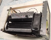
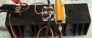
1 case, heat sink, and fan
2 test jig
3 adjustable current draw
4 falsted schematic testing
5 MSOP-8
analyzing performance
datasheets and parts
datasheets and parts (not used)
design notes
Falstad circuit simulations
last updated 06/19/2025 at 14:40:47 by make_www_index.command version 2025.05.20.B