Air Conditioning
AIR CONDITIONINGThe A/C refrigerant system is a clutch cycling orifice tube type. The system consists of the following components:
- A/C compressor
- A/C clutch
- A/C condenser core
- A/C evaporator core
- A/C charge port valve (high side)
- A/C charge port valve (low side)
- connecting refrigerant lines
- function selector switch
- suction accumulator
The refrigerant system operation is controlled by the following:
- A/C evaporator core orifice
- A/C cycling switch
- A/C compressor pressure relief valve
- A/C pressure cut-off switch
- A/C clutch relay
- Powertrain control module (PCM)
The refrigerant system incorporates an A/C compressor controlled by an A/C cycling switch.
The A/C cycling switch senses A/C evaporator core pressure to control A/C compressor operation.
An A/C compressor pressure relief valve is installed in the A/C manifold and tube assembly (3.0L (4V) engine), on the discharge port of the A/C compressor (2.3L engine) to protect the refrigerant system against excessively high refrigerant pressures.
An A/C evaporator core orifice is installed in the condenser-to-evaporator line to meter the liquid and vapor mixture refrigerant into the A/C evaporator core.
A/C Compressor and Clutch Assembly
NOTE:
- Internal A/C compressor components are not repaired separately. Install a new FS-10 A/C compressor only as an assembly. The A/C clutch, A/C clutch pulley, A/C clutch field coil and the shaft seals are repairable.
- Installation of a new suction accumulator is not required when repairing the air conditioning system except when there is physical evidence of system contamination from a failed A/C compressor or damage to the suction accumulator.
The FS-10 A/C compressor has the following characteristics:
- A 10-cylinder swash plate design using the tangential design mount.
- Displacement of 170 cc (10.4 cubic inches).
- A one-piece lip-type seal (repaired from the front of the A/C compressor) is used to seal the compressor at the shaft opening in the assembly.
- Five double-acting pistons operate within the cylinder assembly. The pistons are actuated by a swash plate that changes the rotating action of the shaft to a reciprocating force.
- Reed-type discharge valves are located between the cylinder assembly and the head at each end of the A/C compressor.
- The A/C compressor uses PAG Compressor Oil YN-12-C or equivalent meeting Ford specification WSH-M1C231-B. This oil contains special additives necessary for the A/C compressor.
- The A/C compressor oil from vehicles equipped with an FS-10 A/C compressor may have a dark color while maintaining a normal oil viscosity. This is normal for this A/C compressor because carbon from the piston rings discolors the oil.
The magnetic A/C clutch has the following characteristics:
- It drives the compressor shaft.
- When battery positive voltage (B+) is applied to the A/C clutch field coil, the clutch disc and hub assembly is drawn toward the A/C clutch pulley.
- The magnetic force locks the clutch disc and hub assembly and the A/C clutch pulley together as one unit, causing the compressor shaft to rotate.
- When B+ is removed from the A/C clutch field coil, springs in the clutch disc and hub assembly move the clutch disc away from the A/C clutch pulley.
A/C Compressor Pressure Relief Valve
An A/C compressor pressure relief valve is incorporated in the compressor A/C manifold and tube to:
- relieve unusually high refrigerant system discharge pressure buildups of 3,792 kPa (550 psi) and above.
- prevent damage to the A/C compressor and other system components.
- avoid total refrigerant loss by closing after the excessive pressure is relieved.
Condenser Core
NOTE: Installation of a new suction accumulator is not necessary when repairing the air conditioning system except when there is physical evidence of system contamination from a failed A/C compressor or damage to the suction accumulator.
The condenser core has the following characteristics:
- It is an aluminum fin-and-tube design heat exchanger located in front of the vehicle radiator.
- It cools compressed refrigerant gas by allowing air to pass over the fins and tubes to extract heat and by condensing gas to liquid refrigerant as it is cooled.
Refrigerant Lines
NOTE: Installation of a new suction accumulator is not necessary when repairing the air conditioning system except when there is physical evidence of system contamination from a failed A/C compressor or damage to the suction accumulator.
The condenser to evaporator line contains high-pressure liquid refrigerant upstream of the evaporator core orifice. The A/C manifold and tube assembly is attached to the compressor with O-ring seals.
Evaporator Core
NOTE: Installation of a new suction accumulator is not necessary when repairing the air conditioning system except when there is physical evidence of system contamination from a failed A/C component or damage to the suction accumulator.
The evaporator housing contains the evaporator core. The evaporator core is the plate/fin type with a unique refrigerant flow path.
- A mixture of refrigerant and oil enters the bottom of the evaporator core through the evaporator core inlet tube and is routed so it flows through the partitioned first 4 plate/fin sections.
- The next 4 plate/fin sections are partitioned to force the refrigerant to flow toward the other end of the evaporator core.
- The next 5 plate/fin sections are partitioned to force the refrigerant to flow toward the bottom of the evaporator core.
- Refrigerant then continues through to the remaining 5 plate/fin sections and then moves out of the evaporator core through the evaporator core outlet tube.
- This W-pass flow pattern transfers the flow of refrigerant and oil through the evaporator core.
Evaporator Core Orifice Tube
NOTE: Install a new evaporator core orifice whenever a new A/C compressor is installed.
The evaporator core orifice has the following characteristics:
- color-coded orange
- an orifice diameter of 1.46 mm (0.0575 inch)
- located in the condenser to evaporator line
- changes the high-pressure liquid refrigerant into a low-pressure liquid
- filter screens located on the inlet and outlet ends of the orifice body
- the inlet filter screen acts as a strainer for the liquid refrigerant flowing through the A/C evaporator core orifice
- O-ring seals on the evaporator core orifice prevent the high-pressure liquid refrigerant from bypassing the evaporator core orifice
- adjustment or repair cannot be made to the evaporator core orifice (a new evaporator core orifice must be installed)
Suction Accumulator
NOTE: Installation of a new suction accumulator is not necessary when repairing the air conditioning system except when there is physical evidence of system contamination from a failed A/C compressor or damage to the suction accumulator.
The suction accumulator is mounted to the A/C accumulator bracket. The inlet tube of the suction accumulator is connected to the evaporator outlet tube. The outlet tube is connected to the A/C manifold and tube assembly.
After entering the inlet of the suction accumulator, heavier oil-laden refrigerant contacts an internally mounted dome (which serves as an umbrella) and drips down onto the bottom of the canister.
- A small-diameter oil bleed hole, in the bottom of the vapor return tube, allows the accumulated heavier liquid refrigerant and oil mixture to re-enter the compressor suction line at a controlled rate.
- As the heavier mixture passes through the small diameter liquid bleed hole, it has a second chance to vaporize and recirculate through the A/C compressor without causing compressor damage due to slugging.
- A fine mesh screened filter fits tightly around the bottom of the vapor return tube to filter out refrigerant system contaminant particles.
- A desiccant bag is mounted inside the canister to absorb any moisture which may be in the refrigerant system.
- A fitting located on the top of the suction accumulator is used to attach the A/C cycling switch. A long-travel Schrader-type valve stem core is installed in the fitting so that the A/C cycling switch can be removed without discharging the A/C system.
A/C Cycling Switch
The A/C cycling switch is mounted on a Schrader valve-type fitting on the top of the suction accumulator.
- A valve depressor, located inside the threaded end of the A/C cycling switch, presses in on the Schrader valve stem.
- This allows the suction pressure inside the suction accumulator to control the operation of the A/C cycling switch.
- The electrical switch contacts open when the suction pressure drops to 145-165 kPa (21-24 psi).
- The contacts close when the suction pressure rises to 200-317 kPa (29-46 psi).
- When the A/C cycling switch contacts close, the signal to energize the A/C clutch is sent to the powertrain control module (PCM) which energizes the A/C relay and supplies B+ voltage to the A/C clutch field coil.
- When the A/C cycling switch contacts open, the A/C clutch field coil is de-energized and compressor operation stops.
- The A/C cycling switch controls the A/C evaporator core pressure at a point where the plate/fin surface temperature is maintained slightly above freezing.
- This prevents icing of the A/C evaporator core and blockage of airflow.
- It is not necessary to discharge the refrigerant system to remove the A/C cycling switch.
High Pressure Cut-off Switch
The high pressure cut-off switch is used to interrupt A/C compressor operation in the event of high system discharge pressures.
- The high pressure cut-off switch is mounted on a Schrader valve-type fitting on the high pressure side of the condenser to evaporator line.
- A valve depressor, located inside the threaded end of the high pressure cut-off switch, is used to monitor the compressor discharge pressure.
- It is not necessary to discharge the refrigerant system to remove the A/C pressure cut-off switch.
- The high pressure cut-off switch has 2 sets of contacts. One electrical contact is normally closed.
- When the compressor discharge pressure rises to approximately 3,103 kPa (450 psi), the switch contacts open, disengaging the A/C compressor.
- When the pressure drops to approximately 1,724 kPa (250 psi), the contacts close to allow operation of the A/C compressor.
The switch contains a second set of electrical contacts used for high-speed fan control.
- When the compressor discharge pressure reaches approximately 2,241 kPa (325 psi), these contacts close and engage the high-speed fan control.
- When the pressure drops to approximately 1,896 kPa (275 psi), the contacts again open and the high speed fan control is disengaged.
Spring Lock Coupling:
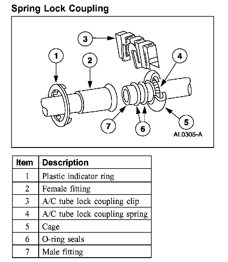
Spring Lock Coupling
The spring lock coupling is a refrigerant line coupling held together by a garter spring inside a circular cage.
- When the coupling is connected together, the flared end of the female fitting slips behind the garter spring inside the cage of the male fitting.
- The garter spring and cage then prevent the flared end of the female fitting from pulling out of the cage.
- The O-ring seals are green in color and are made of a special material.
- Use only the specified green O-ring seals listed in the Master Parts Catalog for the spring lock coupling.
- A plastic indicator ring is used on the spring lock couplings of the A/C evaporator core to indicate, during vehicle assembly, that the coupling is connected. Once the coupling is connected, the indicator ring is no longer necessary but remains captive by the coupling near the cage opening.
- An A/C tube lock coupling clip may be used to secure the coupling but is not necessary.
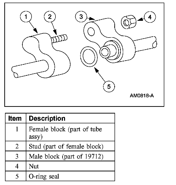
A/C Line (Peanut) Fitting
The A/C line (peanut) fitting is an integral part of the refrigeration line or component.
- The male and female blocks of the air conditioning line (peanut) fitting are retained with a nut.
- An O-ring seal is installed around the tube on the male block.
- The female and male blocks are welded to the tubes and are not adjustable.
- When correctly assembled the male and female fittings should be flush.