Installation
Engine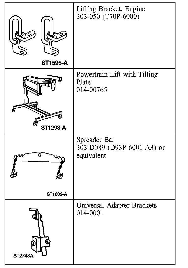
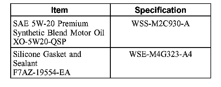
Special Tool(s)
Material
Installation
WARNING: Do not smoke or carry lighted tobacco or open flame of any type when working on or near any fuel-related component. Highly flammable mixtures are always present and may be ignited, resulting in possible personal injury.
WARNING: Fuel in the fuel system remains under high pressure even when the engine is not running. Before repairing or disconnecting any of the fuel system components, the fuel system pressure must be relieved to prevent accidental spraying of fuel, causing personal injury or a fire hazard.
All vehicles
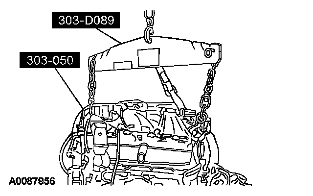
1. Using the special tools, align the engine with the transaxle.
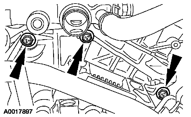
2. Install the 7 transaxle bolts.
^ Tighten to 40 Nm (30 ft. lbs.).
3. CAUTION: Do not allow the engine oil pan to rest on the powertrain lift.
Using the special tools, secure the engine to the powertrain lift.
4x4 vehicles
4. Position the power take off, attach the pin-type retainer and install the bolt.
^ Tighten to 14 Nm (10 ft. lbs.).
5. Install the halfshaft support bracket and the bolts.
^ Tighten to 48 Nm (35 ft. lbs.).
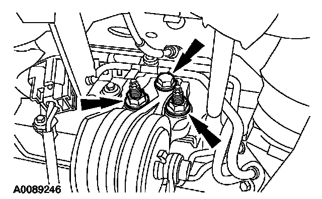
6. Install a new gasket and the RH exhaust manifold and nuts.
^ Tighten in the sequence shown to 20 Nm (15 ft. lbs.).
All vehicles
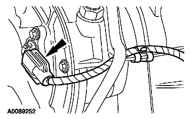
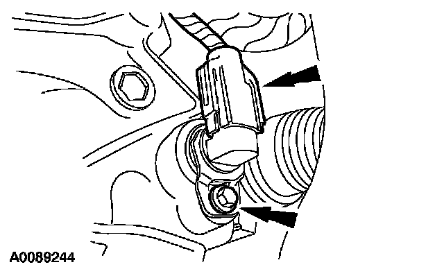
7. Connect the turbine speed sensor (TSS) electrical connector.
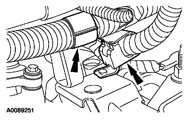
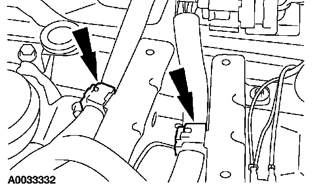
8. Attach the transaxle control harness to the brackets.
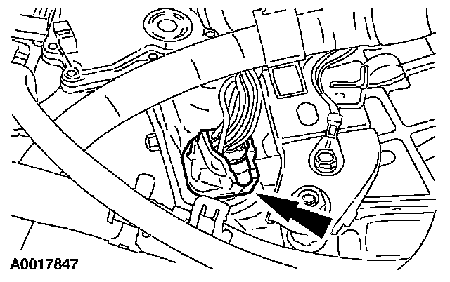
9. Connect the transaxle wiring harness electronic control switch electrical connector.
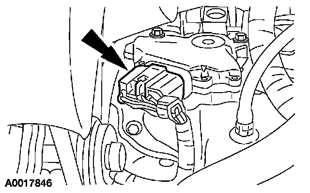
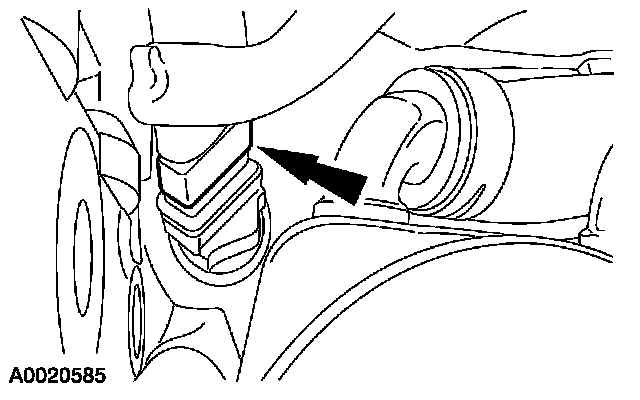
10. Connect the transmission range (TR) sensor electrical connector.
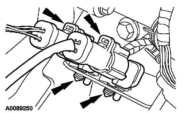
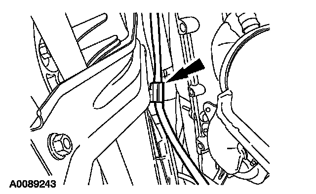
11. Attach the pin-type retainers to the transaxle support bracket and connect the heated oxygen sensor (HO2S) and catalyst monitor sensor electrical connectors.
12. Position the powertrain into the vehicle.
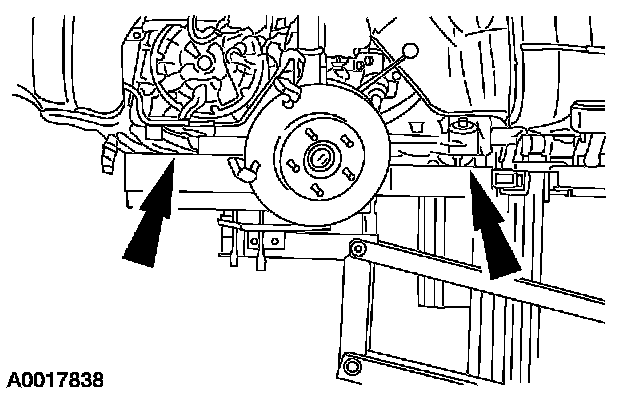
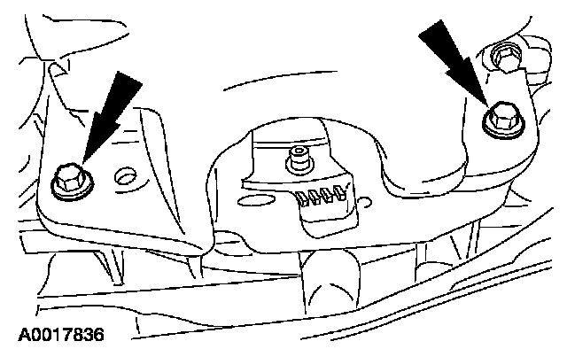
13. Install the front engine support nuts.
^ Tighten to 55 Nm (41 ft. lbs.).
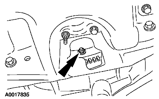
14. Install the rear transaxle support bolt.
^ Tighten to 103 Nm (76 ft. lbs.).
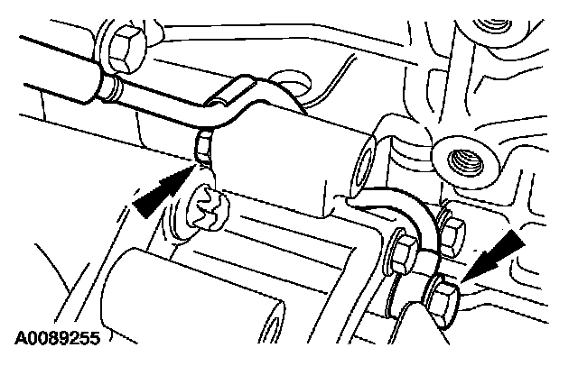
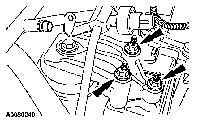
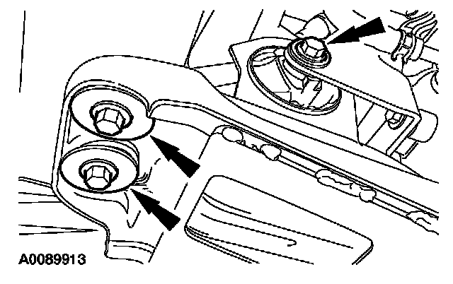
15. Position the RH transaxle support insulator and install the bolt and nuts.
^ Tighten to 90 Nm (66 ft. lbs.).
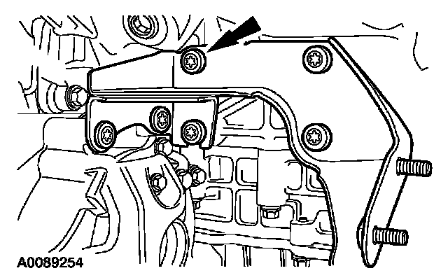
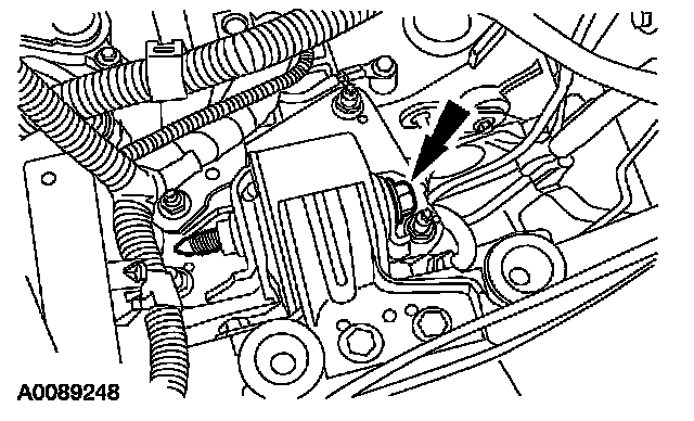
16. Install the RH transaxle support insulator bolt.
^ Tighten to 115 Nm (85 ft. lbs.).
17. NOTE: Clean and decrease all sealing surfaces with metal surface cleaner.
NOTE: The oil pan must be installed and the bolts tightened within four minutes of the sealant application.
Apply a 10-mm (0.39 inch) dot of silicone gasket and sealant to the front cover-to-cylinder block sealing surface.
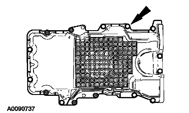
18. Position the oil pan and gasket and loosely install the bolts and stud bolts.
19. Install the 2 oil pan-to-transaxle bolts.
^ Tighten to 40 Nm (30 ft. lbs.).
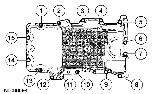
20. Tighten the oil pan bolts in the sequence shown to 25 Nm (18 ft. lbs.).
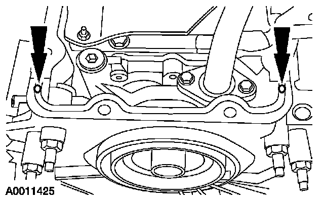
21. Install the 4 torque converter nuts.
^ Tighten to 40 Nm (30 ft. lbs.).
22. Install the torque converter inspection cover.
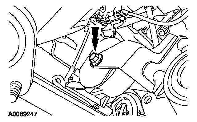
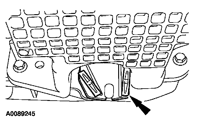
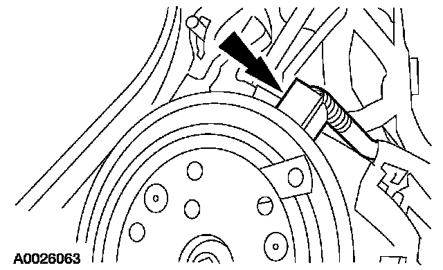
23. Install the output shaft speed (OSS) sensor and the bolt and connect the electrical connector.
^ Tighten to 13 Nm (10 ft. lbs.).
24. Attach the HO2S wiring retainer to the radiator center support.
25. If equipped, connect the engine block heater electrical connector.
26. Attach the wiring harness retainers from the battery tray bracket.
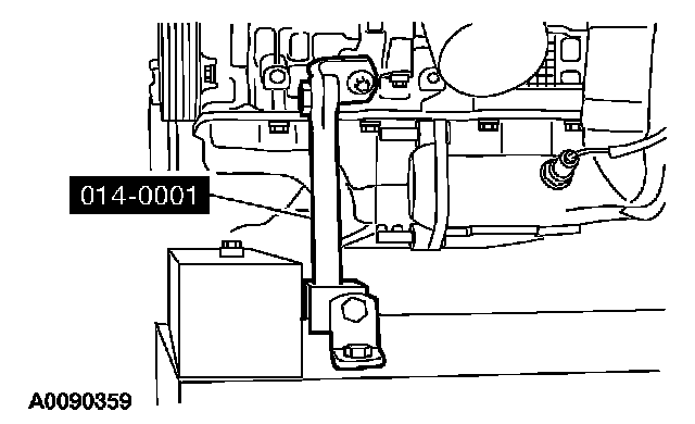
27. Position the ground strap and the electrical connector and install the bolts.
^ Tighten to 10 Nm (89 inch lbs.).
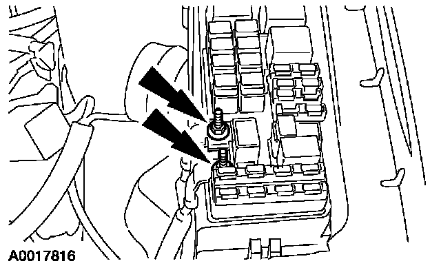
28. Install the cables and the nuts.
^ Tighten to 12 Nm (9 ft. lbs.).
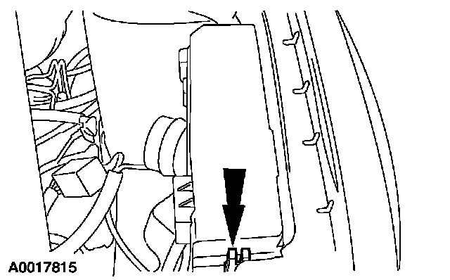
29. Install the power distribution box cover.
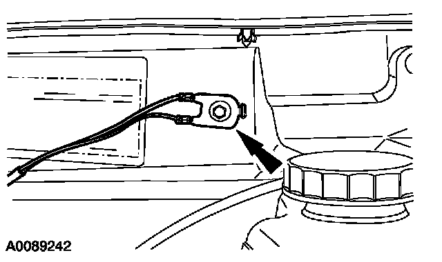
30. Attach the ground wire and install the bolt.
^ Tighten to 10 Nm (89 inch lbs.).
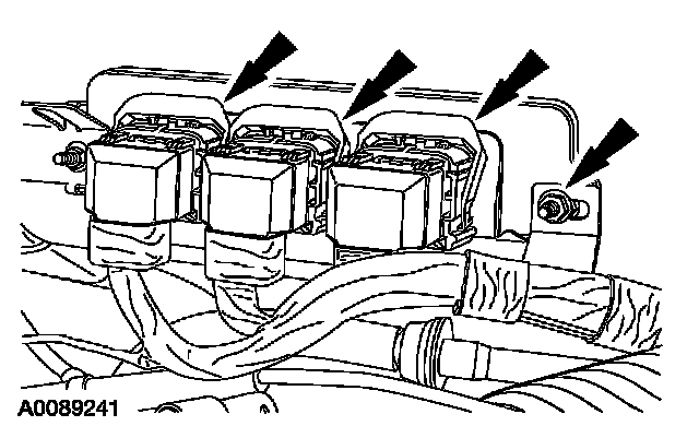
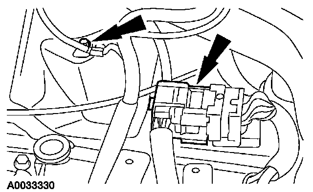
31. Position the wiring and install the nut. Connect the powertrain control module (PCM) electrical connectors.
^ Tighten to 8 Nm (71 inch lbs.).
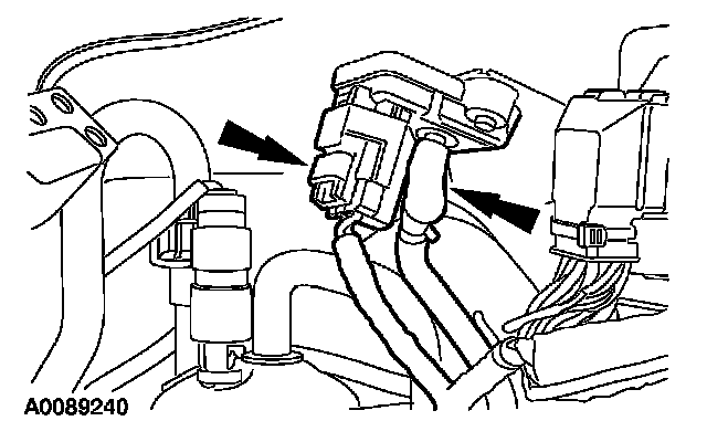
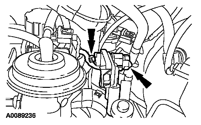
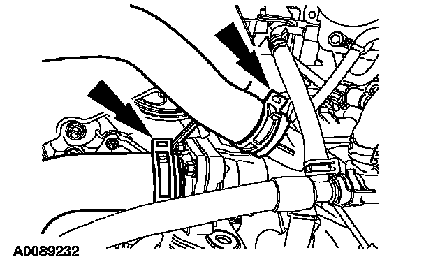
32. Connect the manifold absolute pressure (MAP) sensor electrical connector and vacuum tube.
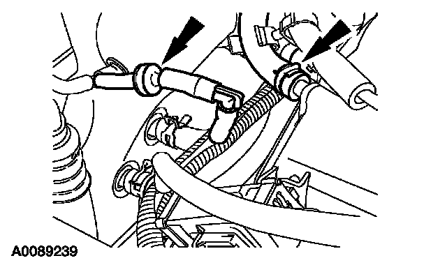
33. Connect the brake booster vacuum tube and the vacuum reservoir tube.
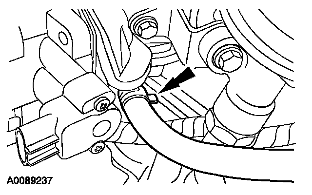
34. Connect the evaporative emissions purge valve vacuum tube to the intake manifold.
^ Attach the vacuum tube retainer to the transmission fill tube.
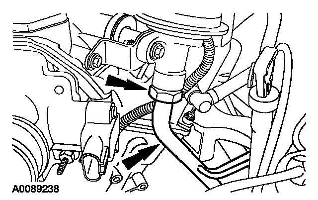
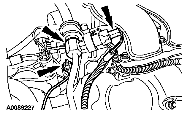
35. Position the exhaust gas recirculation (EGR) tube and loosely install the fittings.
^ Tighten the EGR tube-to-EGR valve fitting to 40 Nm (30 ft. lbs.).
36. Connect the differential pressure feedback EGR sensor electrical connector and attach the pin-type retainer.
37. Position the gearshift cable bracket and install the bolts.
^ Tighten to 19 Nm (14 ft. lbs.).

38. Attach the wiring harness pin-type retainer to the gearshift cable bracket.
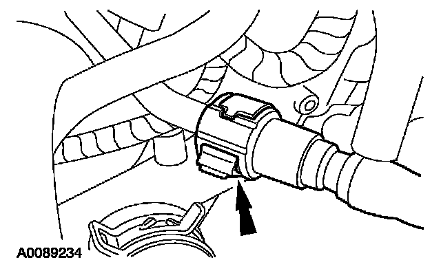
39. NOTE: Make sure the collar on the fuel tube is inserted fully into the quick release coupling before the locking tang is locked.
NOTE: Apply clean engine oil to the end of the tube before inserting a tube into the connector.
Connect the fuel tube quick connect coupling.
^ Connect the quick lock coupling to the tube.
^ Press the quick connect coupling locking tangs into position.
^ Pull on the fitting to make sure it is fully engaged.
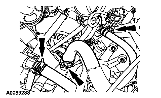
40. Connect the heater hoses and the throttle body coolant hose.
41. Connect the hoses.
42. Position the accelerator and speed control cables and bracket. Install the nut.
^ Tighten to 10 Nm (89 inch lbs.).
43. Position the bracket and install the bolts.
^ Tighten to 10 Nm (89 inch lbs.).
^ Connect the accelerator cable and the speed control actuator cable.
44. Position the accelerator cable snow shield and install the bolts.
^ Tighten to 10 Nm (89 inch lbs.).
45. Tighten the EGR tube-to-RH catalytic converter fitting to 40 Nm (30 ft. lbs.).
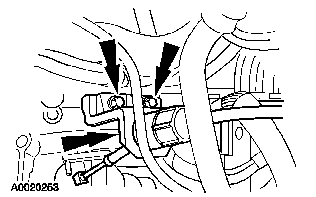
46. Connect the 2 transmission cooler tubes.
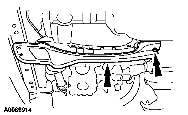
47. Install the cross brace and the rear nut.
^ Tighten to 175 Nm (129 ft. lbs.).
48. Install the bolt for the transaxle mount and install the two bolts for the cross brace.
^ Tighten the transaxle mount bolt to 115 Nm (85 ft. lbs.).
^ Tighten the cross brace bolts to 90 Nm (66 ft. lbs.).
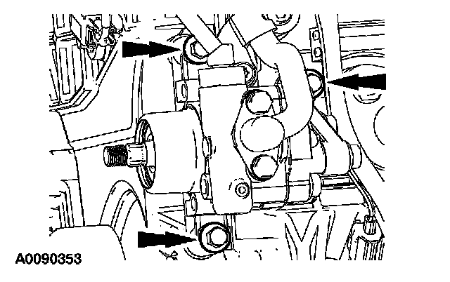
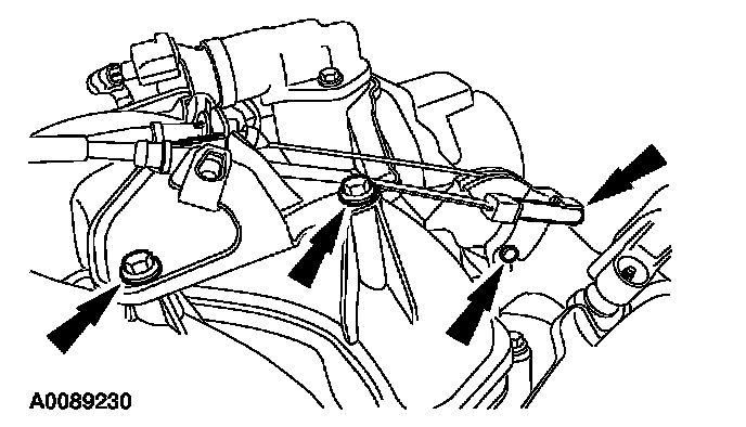
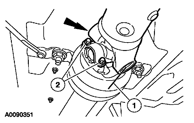
49. Position the power steering pump and install the bolts.
^ Tighten to 25 Nm (18 ft. lbs.).
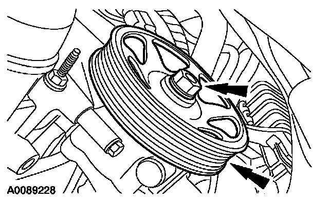
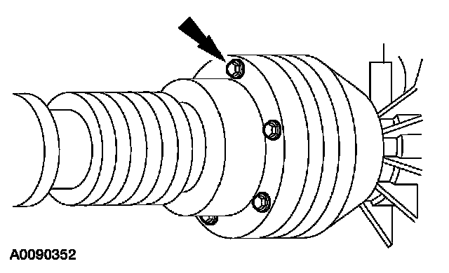
50. Install the power steering pump pulley and the nut.
^ Tighten to 49 Nm (36 ft. lbs.).
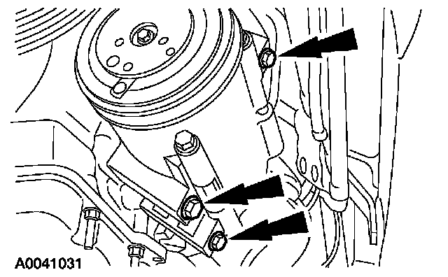
51. Install the A/C compressor and the bolts.
^ Tighten to 25 Nm (18 ft. lbs.).
52. Connect the A/C clutch field coil electrical connector.
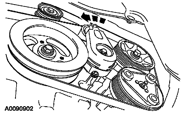
53. Rotate the accessory drive belt tensioner clockwise and install the accessory drive belt.
4x4 vehicles
54. CAUTION: Do not reuse the bolts and straps for the center U-joint. Install new bolts and straps or damage to the vehicle may occur.
NOTE: There is a difference in the length of the head of the replacement yoke strap bolts from the production bolts. The longer head pinion bolts can be used in either location.
Install the driveshaft.
1. Align the driveshaft with the index marks.
2. Install the new straps and bolts.
^ Tighten to 23 Nm (17 ft. lbs.).
55. CAUTION: Do not reuse the CV joint bolts and washers. Install new bolts and washers or damage to the vehicle may occur.
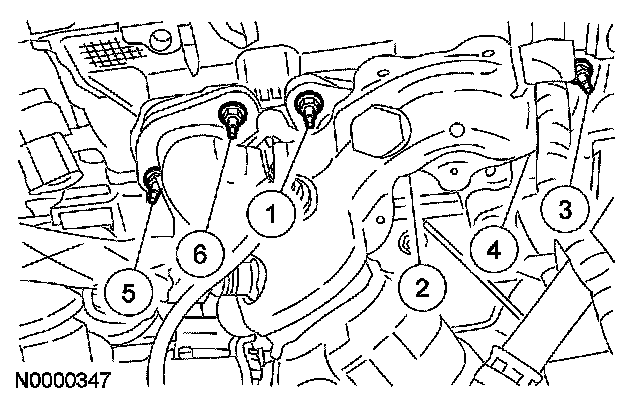
Install the 6 front driveshaft-to-power take off bolts and washers.
^ Tighten to 37 Nm (27 ft. lbs.).
All vehicles
56. Install the LH halfshaft.
57. Install the generator.
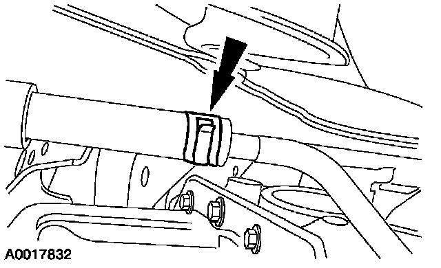
58. Install the exhaust system flexpipe.
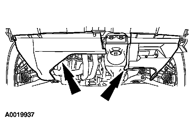
59. Install the lower radiator air deflectors.
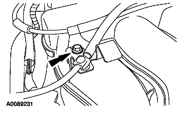
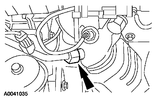
60. Position the power steering hose bracket and install the nut.
^ Tighten to 25 Nm (18 ft. lbs.).
^ Connect the power steering pressure (PSP) switch electrical connector.
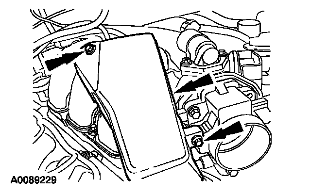
61. Install the air cleaner outlet pipe and air cleaner.
62. Install the battery tray.
63. Fill and bleed the cooling system.
64. Fill the engine with clean engine oil.