Cylinder Head - LH
Cylinder Head - LH
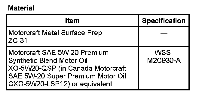
Material:
Removal
NOTICE: During engine repair procedures, cleanliness is extremely important. Any foreign material, including any material created while cleaning gasket surfaces that enters the oil passages, coolant passages or the oil pan, can cause engine failure.
1. With the vehicle in NEUTRAL position it on a hoist. For additional information refer to Maintenance/Vehicle Lifting. Vehicle Lifting
2. Remove the lower intake manifold. For additional information refer to Engine/Intake Manifold. Intake Manifold
3. Remove the LH exhaust manifold. For additional information refer to Powertrain Management/Emission Control Systems/Catalytic Converter. Catalytic Converter
4. Remove the coolant bypass tube. For additional information refer to Cooling System/Thermostat Bypass Hose. Thermostat Bypass Hose
5. Remove the LH camshafts. For additional information refer to Engine/Camshaft, Lifters and Push Rods/Camshaft. Camshaft
6. Remove the oil level indicator and tube. For additional information refer to Engine/Engine Lubrication/Engine Oil Dip Stick - Dip Stick Tube. Engine Oil Dip Stick - Dip Stick Tube
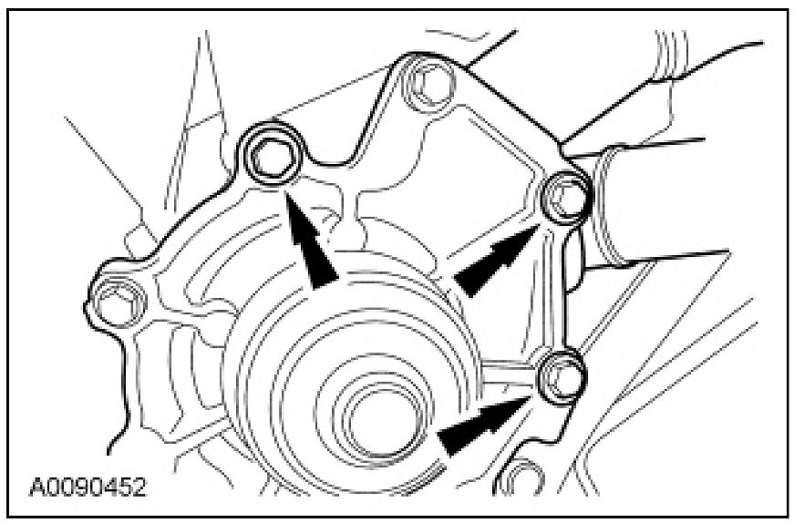
7. Remove the 3 bolts and position the coolant pump aside.
8. NOTICE: The camshaft roller followers must be installed in their original positions.
Remove the camshaft roller followers.
9. NOTICE: The hydraulic lash adjusters must be installed in their original positions.
Remove the hydraulic lash adjusters.
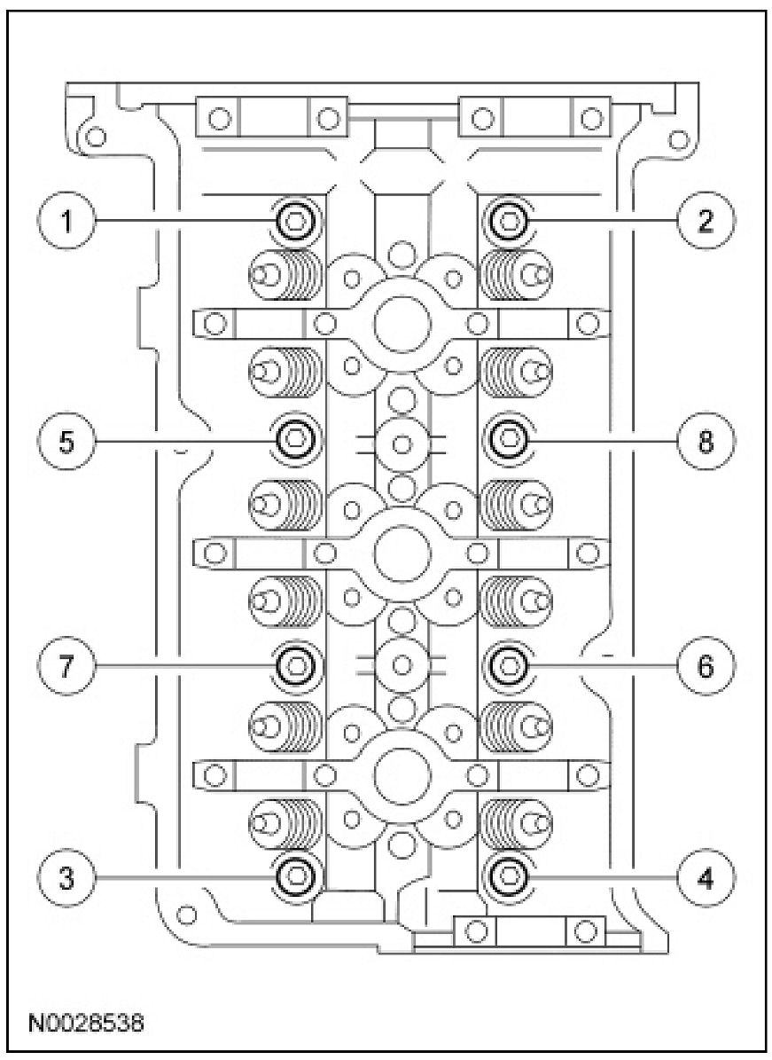
10. NOTE: New cylinder head bolts must be installed. They are torque-to-yield designed and cannot be reused.
Remove the bolts in the sequence shown.
11. Remove the cylinder head and the cylinder head gasket.
- Discard the gasket and the bolts.
12. NOTICE: Do not use metal scrapers, wire brushes, power abrasive discs or other abrasive means to clean the sealing surfaces. These tools cause scratches and gouges which make leak paths.
Clean the cylinder head gasket surfaces with a plastic scraping tool and metal surface prep.
13. Support the cylinder head on a bench with the head gasket side up. Check the cylinder head distortion and the cylinder block distortion. For additional information refer to Cylinder Head Assembly/Service and Repair/Procedures. Procedures
Installation
1. Clean the cylinder head bolt holes in the cylinder block. Make sure all coolant oil or other foreign material is removed.
2. Position a new gasket and the cylinder head.
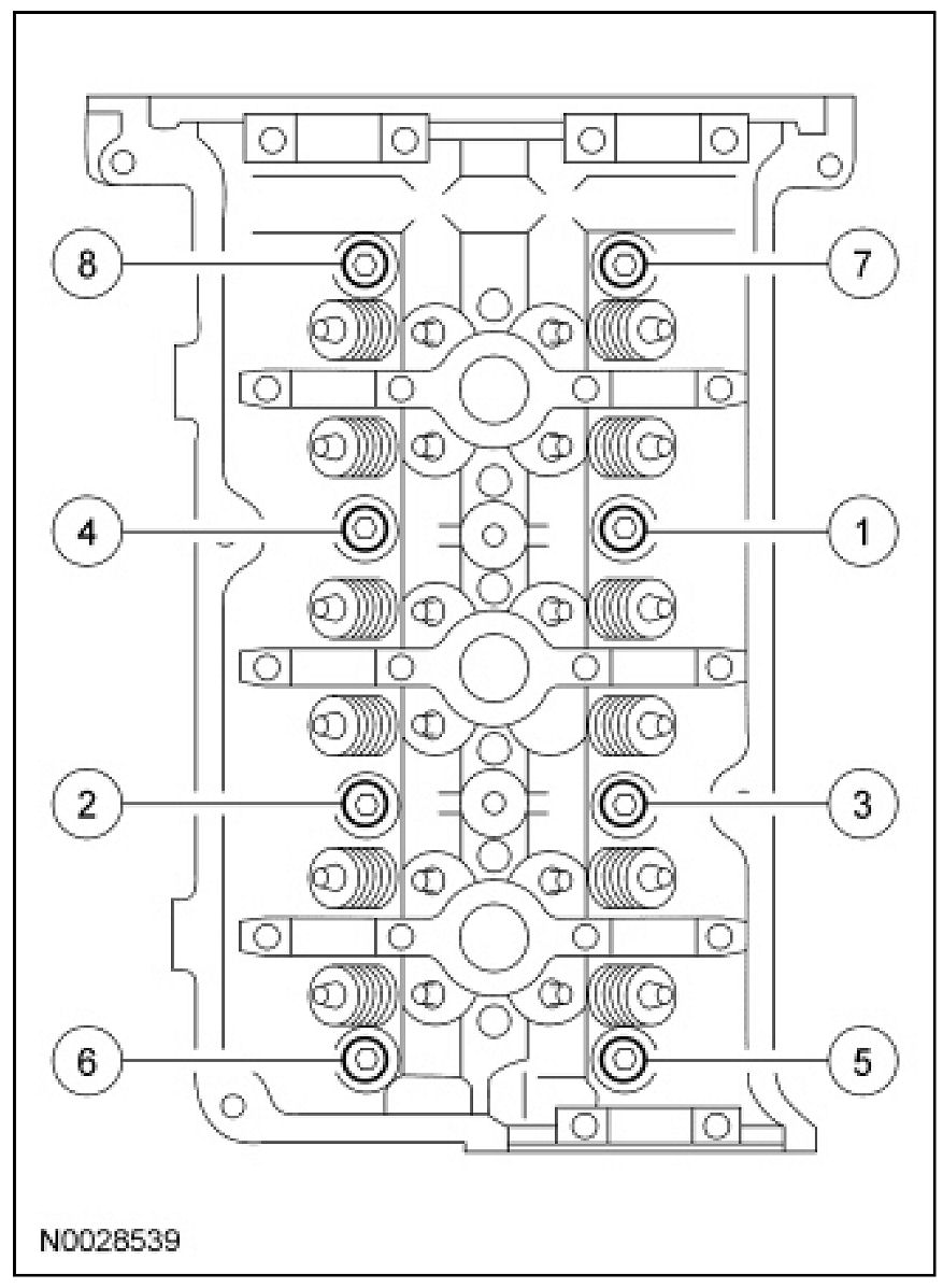
3. NOTE: New cylinder head bolts must be installed. They are torque-to-yield designed and cannot be reused.
Install the bolts and tighten in 6 stages in the sequence shown.
- Stage 1: Tighten to 40 Nm (30 lb-ft).
- Stage 2: Tighten bolts 90 degrees.
- Stage 3: Loosen one full turn.
- Stage 4: Tighten to 40 Nm (30 lb-ft).
- Stage 5: Tighten 90 degrees.
- Stage 6: Tighten 90 degrees.
4. NOTICE: The hydraulic lash adjusters must be installed in their original positions.
Install the hydraulic lash adjusters.
- Lubricate the hydraulic lash adjusters with clean engine oil.
5. NOTICE: The camshaft roller followers must be installed in their original positions.
Install the camshaft roller followers.
- Lubricate the camshaft roller followers with clean engine oil.
6. Position the coolant pump and install the bolts.
- Tighten to 10 Nm (89 lb-in).
7. Install the oil level indicator and tube. For additional information refer to Engine/Engine Lubrication/Engine Oil Dip Stick - Dip Stick Tube. Engine Oil Dip Stick - Dip Stick Tube
8. Install the LH camshafts. For additional information refer to Engine/Camshaft, Lifters and Push Rods/Camshaft. Camshaft
9. Install the coolant bypass tube. For additional information refer to Cooling System/Thermostat Bypass Hose. Thermostat Bypass Hose
10. Install the LH exhaust manifold. For additional information refer to Powertrain Management/Emission Control Systems/Catalytic Converter. Catalytic Converter
11. Install the lower intake manifold. For additional information refer to Engine/Intake Manifold. Intake Manifold