back to combiners
importance of panel combiners
importance of panel combiners:
Lets examine and compare power losses for two different panel combining arrangements. For this I would like
to use https://www.rapidtables.com/calc/wire/voltage-drop-calculator.html to calculate power losses. Here are
the ground rules:
- I will consider the delivery wire between panels and controller to be #10 CCA, which should have about the
same resistivity (resistance per foot) as #12 copper of the same length. (1.72e-8 ohms per meter)
- the delivery wire will be 100 feet long, so 200 feet of total delivery wire, round-trip
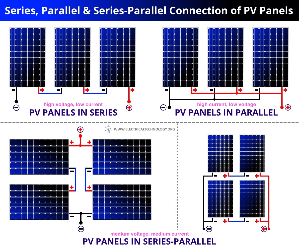
- tests will consider 8 total panels, either in two strings of 4 in parallel, or all 8 in parallel
- voltage per panel will be assumed to be at its maximum power point, so Vmpp = 14.6 volts
- 100 panels will be assumed to be delivering 75% of their rated power, about what you could get in Iowa.
Eight 100w panels producing 75% of rated power would be 600 watts. Eight panels all in series would produce
41 amps at 14.6 volts. If placed in two strings of 4, it would produce 10.2 amps at 58.4 volts.
Total round-trip resistance of solid aluminum wire would be 0.317 ohms. I measured 100 feet of my CCA with
silver-plated PP35 contacts at 0.28 ohms total (which was probably lower than just aluminum due to the copper
cladding) so I will be going with that instead.
The drop calculator can't be used in this case though because it produces nonsense numbers. The problem is
that when you add so much resistance in line, it produces a dramatic drop in current. Current isn't constant
so we need to adjust that. The easiest approach is to consider the load resistance. We know the voltage,
and we know what we want the power draw to be (with no transmission losses) so we can calculate the load
resistance at the panel input on the charge controller. If we're getting our 600 watts at 14.6 volts, load
resistance is v^2/p = 0.355 ohms. At 58.4 volts, it's 5.68 ohms. Since we're not changing the battery's
charge state (and thus charge demand) for the comparison, I will assume these resistances do not change based
on the added resistance of the distribution wire. Either way the battery still has a charge resistance, and
it's naturally going to charge slower if current flow through it is reduced.
So now we can find ACTUAL current flow based on the new total resistance. This changes the 14.6 volt panel
total resistance to 0.317+0.355 ohms = 0.672 ohms. At 14.6 volts, current flow will drop from 41 to 21.7
amps, and power consumed by the load will be i^2*r = 167 charging watts, which is 27% of direct connection.
This changes the 58.4 volt panel total resistance to 0.317+5.68 ohms = 5.997 ohms. At 58.4 volts, current
flow will drop from 10.2 to 9.74 amps, and power consumed by the load will be i^2*r = 539 charging watts,
which is 89% of direct connection.
Note that at 14.6 volts we're not burning up 600-167 watts of power as heat in the transmission line. The
much larger contribution to the drop in charge speed/power is due to the drop in current flow. Cutting the
voltage to 1/4 about cuts the current in half, which quarters the power produced by the panels. And then only
about 1/2 of that remaining power is consumed by the battery, with the remainder turning to heat in the wire.
THIS is why it's important to keep panel voltage as high as possible if you have a long distribution line to
your controller. Since loss is tied to the square of the current, percentage losses and charging speed will
be less affected as the battery gets more charged and demand goes down, so you won't be stuck down at 27%
the entire time you're charging the battery, but that's where you will start out.
seriess parallel options:
highest resolution images
last updated 10/11/2023 at 10:45:11