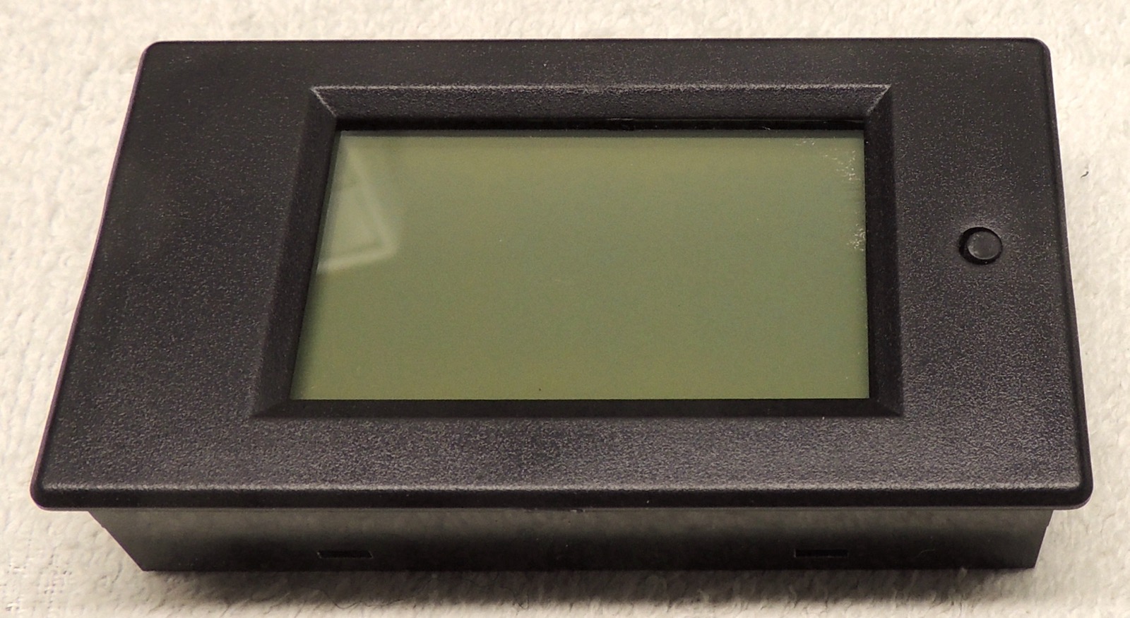
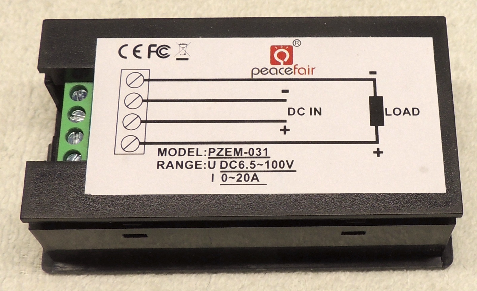
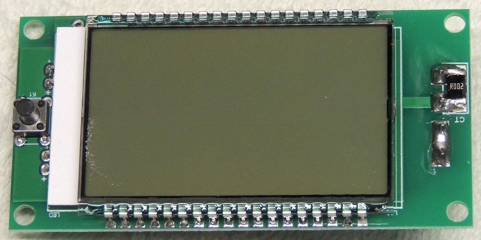
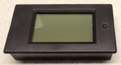
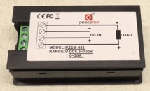
back to PZEM-031 power display
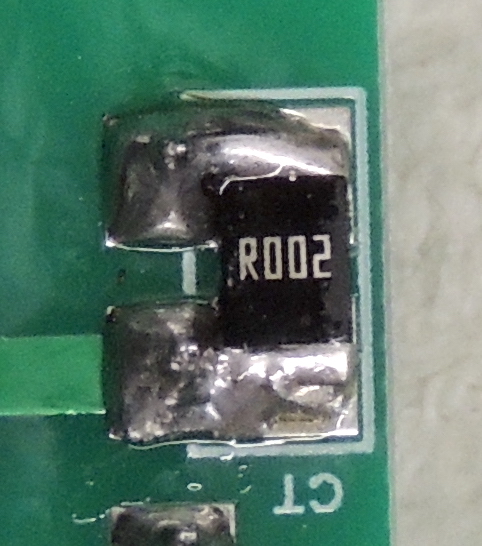
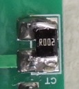
meter shunt adjusting
meter shunt adjusting:
When I put two meters into a single box to compare power flow in both directions, I discovered that the meters
weren't as accurate as I wanted them to be. With a test load drawing 10.0 amps (at 13.8v) one meter read
9.7 amps and the other meter (in the other direction of course) read 9.5 amps. So... the good news is they
are reading low, meaning the shunt resistors are generating slightly less voltage drop than the meter wants,
which means I can shave a little off the resistors to increase their resistance and recalibrate it. The bad
news is... I have to shim the shunt resistors. Doesn't look like a lot of fun.
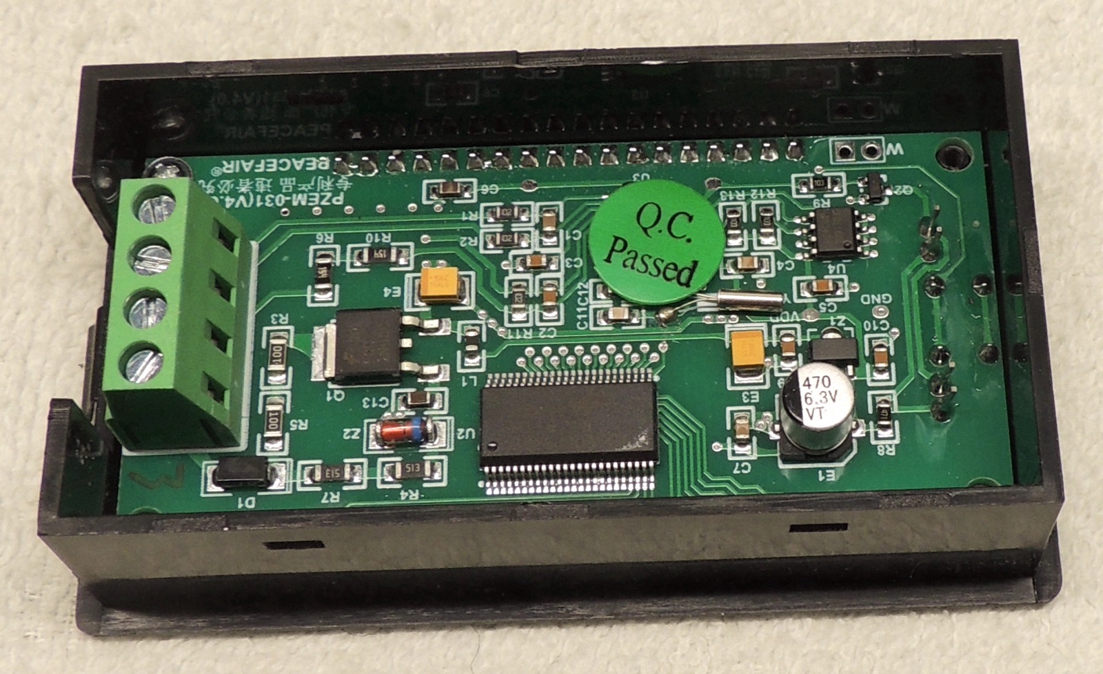
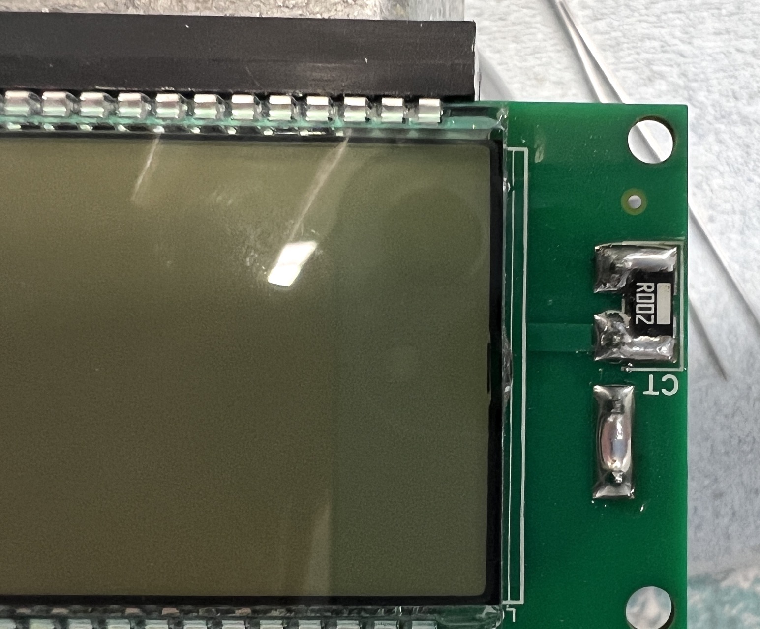
But THIS is why it's common to see a small slot carved in higher current shunts. They manufacture them with
a slightly lower resistance than required, then they trim them individually after manufacture, to bring them
within tolerance on a test current measurement.
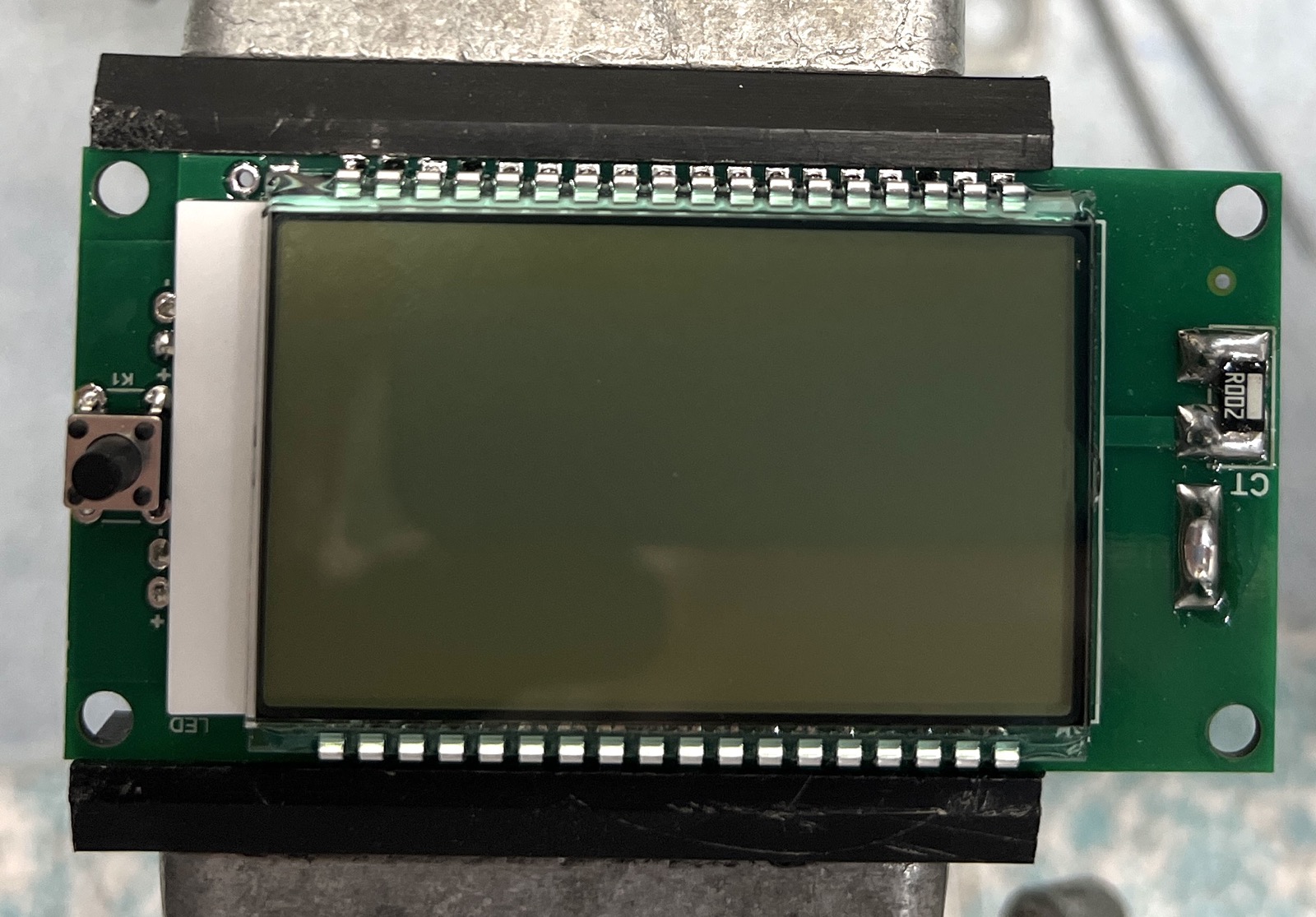
I am ASSUMING these PeaceFair meters are doing that in software, and have some sort of last-step in their
manufacturing where they load the meter up with a test voltage and current, and signal to the microcontroller
to set its internal offsets so that they display the correct values. But I have no idea how to perform this
post-manufacture calibration, or even if they DO it. So I have to fix it "the hard way". It would be so much
easier if I could access that step in the menu on the meter, but I wasn't able to find anything like it.
|
|
|

|
|
|
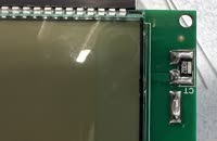
| 1 top |
2 bottom |
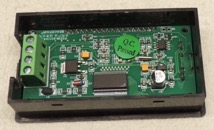
3 opened |
4 board removed |
5 shunt closeup |
IMG_2325 |
|
|
|
|
|
|
| IMG_2327 |
|
|
|
|
|
highest resolution images
last updated 11/08/2025 at 22:10:41 by make_www_index.command version 2025.11.05.A