back to Hornet electric
hornet tail mod
hornet tail mod:
The purpose of this modification is to remove all slop from the tail rotor's pitch adjustment. The stock tail
pitch slider has a lot of slop in it, and you get a new one in the CP kit that's a world better, but the
clevis joint on the pitch slider is just as sloppy. This fixes it.
Tools you will need: small philips screwdriver, large dikes, metric ruler/caliper, x-acto knife with fresh
blade, pliers, drill, sharp 1/16" bit
Supplies you will need: tail pitch slider from CP kit, two ball links, two JR balls, two 2x10mm JR ball link
bolts, two 2mm JR ball link nuts, 1 small wire tie
Step 1: Turn on your tx and rx, and note the angle of the TR blades as best you can. Write this down for
alignment later. One way to measure angle is to fold both tail blades toward each other and to measure the
difference in distance between the tips, along a line parallel with the tail rotor shaft, similar to the 30mm
check done when you assembled your hornet.
Step 2: Remove the tail pitch arm from the hornet, and disengage the linkage from it.
Step 3: Use a pliers to carefully press a JR ball down onto the post on the CP kit's tail pitch slider. Press
it on so that the end that's beveled in for the screw head is facing outward, and only press it on until the
post gets to the deepest spot in the bevel. Do not press it all the way on. Once on, the ball should be firmly
held by the post. Do not use a twisting motion on the post or ball, or you may break it off.
Step 4: pop a ball link onto that ball. Test to make sure it is absolutely free to move, you want it to swivel
around with just gravity as you turn over the tail pitch slider. It will probably be tighter than this though.
Use the pliers to carefully and slowly apply pressure to the sides of the ring inward onto the ball. This will
stretch the plastic a very small amount, widening the link just a little. Squeeze a little and then test it.
Repeat until the link is absolutely free to move. Pop it off and set it aside, use this link a few steps from
now. (this link is now "matched" to this ball)
Step 5: Replace the stock tail pitch slider with the new one in the CP kit. While you have the stock slider
off, check the fit between the pins on the blade grips and the holes in the new slider. This needs to be a
very smooth fit, but is usually binding a bit. If necessary, widen the holes in the slider just an
infinitesimal amount to make sure the pins are free to easily rotate in the holes. Do not oversize the holes,
or you will introduce slop!
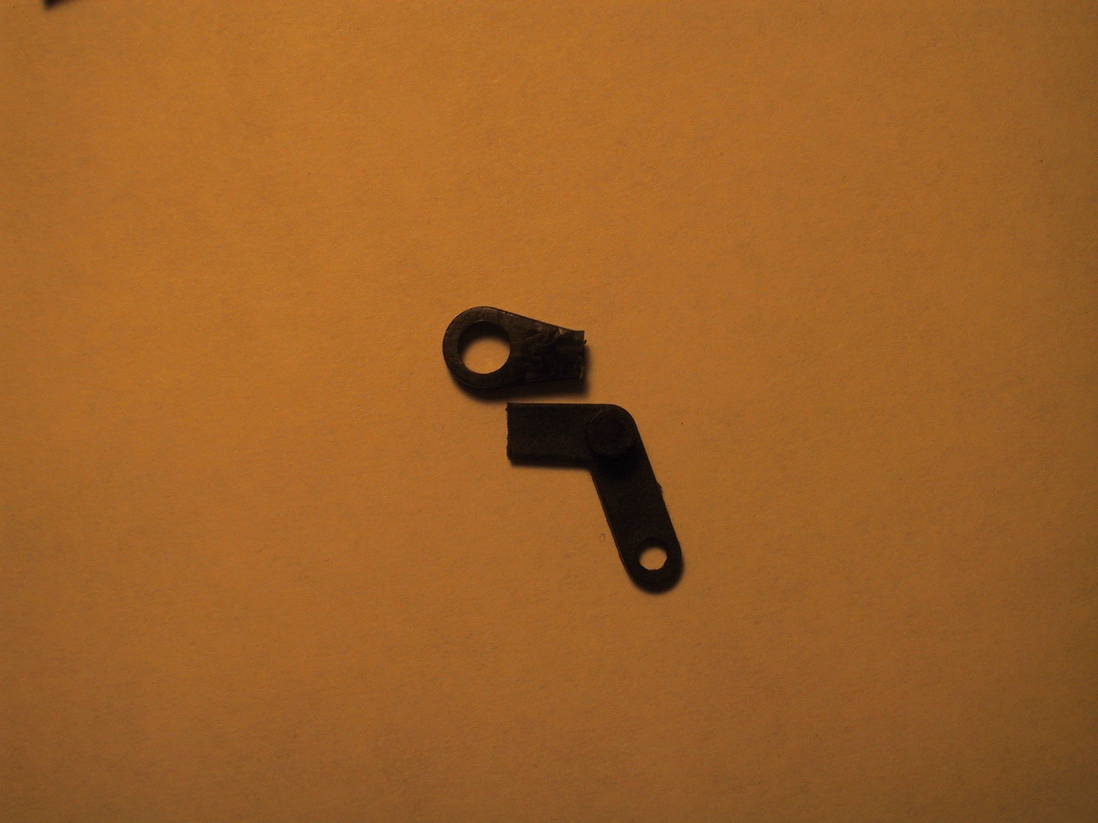
Step 6: Using the dikes, carefully cut the LONG end of the tail pitch arm off so that there is EXACTLY an 8mm
distance between the outer rim of its hinge ring and where you are making the cut. The distance on this is
important, so be careful. We will be flipping this part over, so you are actually turning the linkage end into
the tail pitch end now.
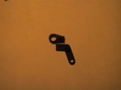
Step 7: Use the x-acto knife to cut the wire rod end of the ball link shorter. Measure carefully 8mm from the
inside rim of the link nearest the rod end, and make the cut there. This part will be getting placed on top of
the tail pitch arm you just cut, and the link's opening needs to begin right at the end of the tail pitch arm
where you cut it short. (see picture)
Step 8: This is a little tricky, so take your time. You need to use the x-acto knife to carefully shave down
the rounded part of one side of the rod end of the ball link so that it is flush with the loop end. It needs
to be flat so it can rest on the tail pitch arm. This will involve removing enough material to juuuust nearly
expose the inside of the rod hole. Shave a small bit off at a time until it's nice and flat.
Step 9: Chuck up the 1/16" bit, make sure it's sharp so it doesn't wander. Drill a hole in the exact center of
the tail pitch arm on the side you cut.
Step 10: Drill a hole in the link you prepared, exactly 1/2 way between the inside rim of the link and the end
you cut off. If done correctly, this hole should exactly match up with the other hole you just made for the
next step.
Step 11: Attach the tail pitch arm and the ball link together using a 2x10mm JR ball link screw. Drive the
screw into the ball link (from the curved side) and into the pitch arm. (from the side where the hinge post
extends) I was going to use some slow CA on this joint as well, but found the plastic is plenty strong enough
to hold the threading the screw is going to give it and keeps both parts solidly fixed together. Put a 2mm
ball link nut on the other end just in case. Don't tighten the bolt too far, avoid crushing down the ball link
or deforming it so that it no longer rests flat on the tail pitch arm. Use the x-acto knife to shave away any
little extension the end of the arm has (where you cut it) so that it does not extend over the opening for
the ball link. (should be fine if you measured accurately earlier)
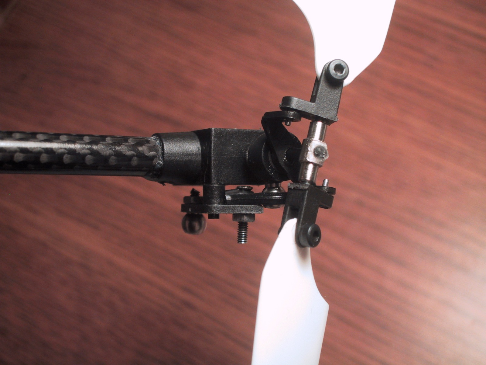
Step 12: Attach a ball to the other end of the tail pitch arm. The ball needs to be on the side opposite the
hinge post. If you used a 2x10mm ball link bolt, you'll need to use the dike to cut off the end of the bolt
after you put the nut on, or it will hit the tail gearbox. Perform the "squeeze" on this link also if needed,
to make sure it moves absolutely free on the ball.
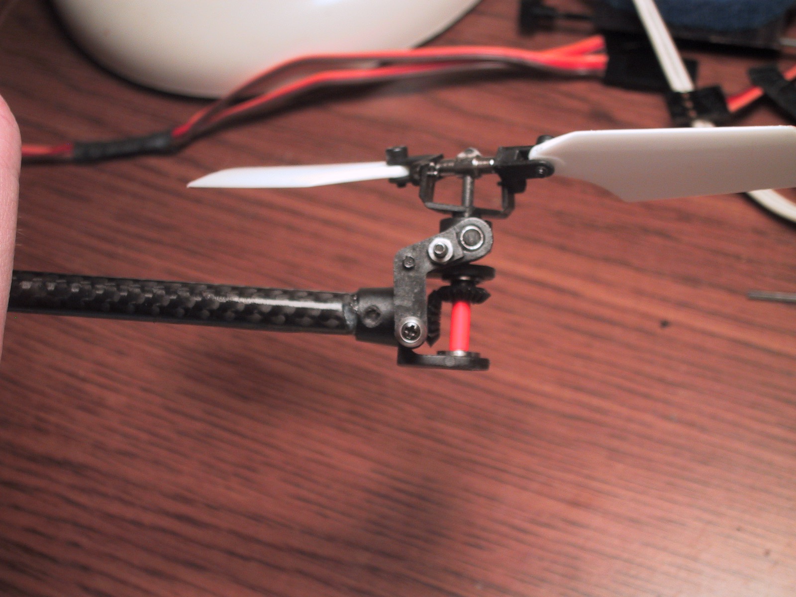
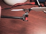
Step 13: Place the tail pitch arm on its post, upside-down. The ball link should be positioned right over the
ball on the new tail pitch slider, snap it on now. Test for free movement throughout the entire range. Having
cut the two parts to exactly 8mm should give you exactly full range of travel. You will have to make
adjustments if the range of travel is unacceptable. (8mm was perfect for my hornet) If it's not extending
outward far enough, you will need to make another ball link 9mm long, and drill the hole 1mm farther toward
the rod end of the link. If it's not extending toward the gearbox enough, you'll need to cut 1mm off the end
of the tail pitch arm, and make a new link with a 7mm cut and drill the hole 1mm toward the link from center.
Step 14: Test the movement of the tail pitch arm on its hinge pin, it should move fairly freely and very
smoothly. (apply oil or light grease to the tail rotor shaft and tail pitch arm hinge shaft if necessary) The
blade pitch should be unmovable without moving the arm. (no "slop")
Step 15: Dissolve out the CA on the servo link that was attached to the tail pitch arm, or use the dike and
just cut it off. (carefully! avoid damaging the CF rod)
Step 16: Take another ball link and measure the depth of the rod hole. Cut the end off the wire tie to exactly
that length. We will be using that bit you just cut off, so throw away the rest of the tie. There should be
serrations on the end of the tie, they have an amazing ability to grip a CF rod. Cut the tie end lengthwise so
that it just perfectly fits into the ball link. There should be a very small gap above and below the tie end
when it's in the link.
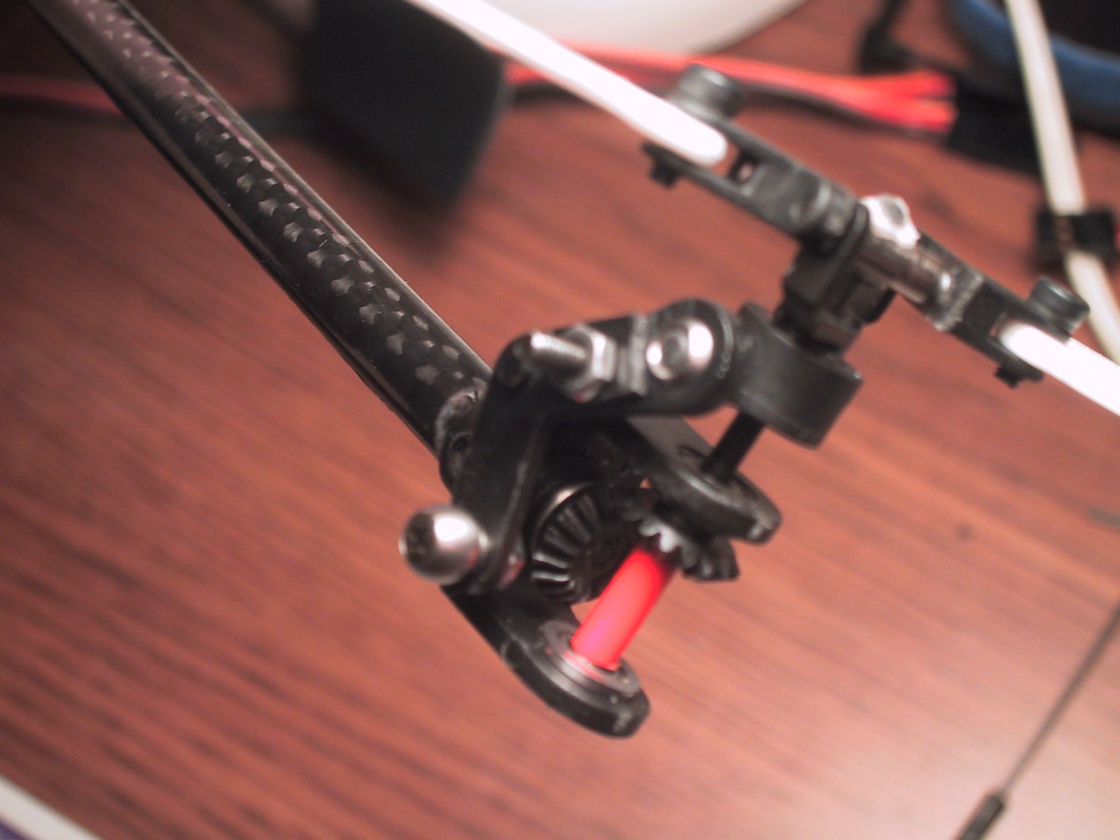
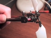
Step 17: Pop the link onto the ball and insert the CF rod. Turn on the tx/rx to re-center the servo if
necessary. Adjust the tail pitch arm so that the blade pitch exactly matches the angle you noted when you
started. The CF rod may be too long. You can either adjust the link at the servo, or trim the CF rod if needed.
Step 18: Carefully measure how much of the CF rod needs to be inserted into the link. Place the wire tie end
against the CF rod and carefully insert the two so that the tie end goes all the way in and the CF rod goes in
as far as you measured. The tie end will probably have a good grip on the wire tie. Dump some slow CA in the
hole if you feel like it. I drilled a small hole into the side of the link (on the tie end side!) and tapped
in a servo horn screw and used that like a grub screw to apply pressure on the tie end to hold the CF rod in
place. (I prefer to leave things adjustable rather than to CA them down)
DONE!! The tail rotor blades should have absolutely no pitch play now. Your gyro will thank you. :-)
|
|
|

|

|
|
| 8mmoverlaplg |
installation1lg |
installation2lg |
installation3lg |
installation4lg |
|
highest resolution images
last updated 05/20/2025 at 15:47:30 by make_www_index.command version 2025.05.20.B