back to constructing my own
3 adjustable current draw
3 adjustable current draw:
I'm in the process of ordering several components to upgrade my current test jig. This includes a "current
shunt monitor" IC that can be placed across a shunt on the high side of the load (at any voltage) and will
also siphon power off that to run the chip. It produces a fixed 20x voltage gain on the shunt, which I should
be able to feed into an op amp network that combines with a selectable voltage from a control knob to drive
the gate on the mosfet(s) to achieve the selected current.
This should also have the benefit of making the control knob linear with respect to load current. (I found
that mosfet current does not rise linearly with increases to gate voltage)
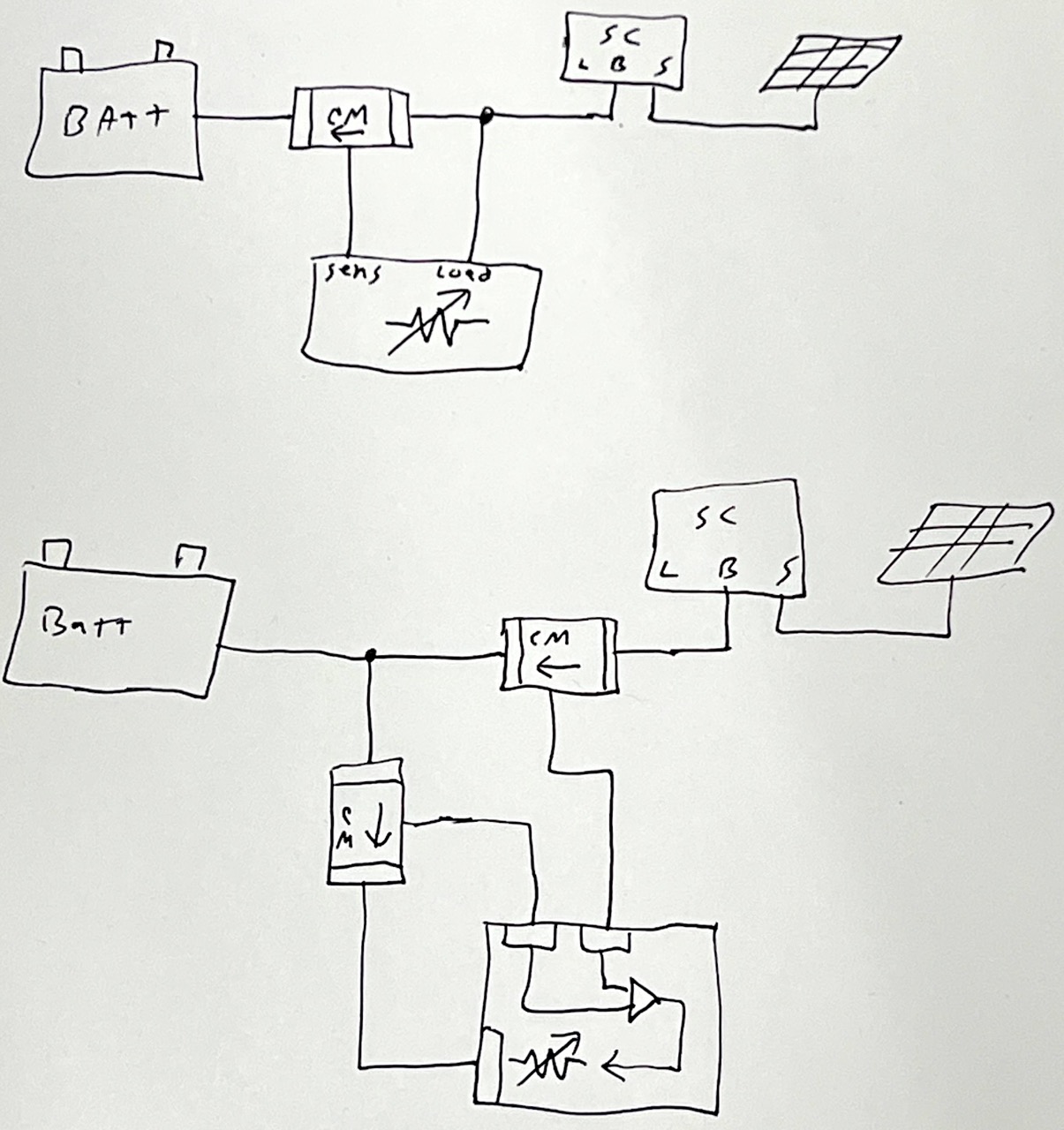
I had another inspiration today. I had been trying to develop a way to divert power going to a battery from a
solar controller. The idea was to sample the power going back from the controller to the battery, and use that
to adjust the load. The problem that presents is it doesn't create any "differential" that can be adjusted with
feedback. My new idea is to add a second current detector going to the load. This would allow me to compare
power coming from the controller with power going to the load, and create a feedback signal (to the mosfets) to
equalize those two currents. It will probably be necessary to have some small fixed load ahead of the mosfets,
to insure there is always a small amont of current drawn even when the solar controller isn't proving power, to
make the mosfets default to fully off.
Another idea I've had is to design this as a multi-function load. Have three modes:
mode 1: low current (variable between 0-10 amps)
using the current monitor on the source branch only, with the negative input from an external control knob that
has its high side set to a value precision trimmed internally to limit to 10 amps. fan off.
mode 2: high current (variable between 0-100+ amps), with a different trimmer set to 100 amps instead of 10, and
the fan on.
mode 3: dynamic (zero net current back into battery), for solar and other charge testing. +/- input are from
the current monitors on the source and on the battery. (also with the fan on)
To protect the mosfet gates, I should probably put a 1meg resistor, 10uF cap, .01uF cap, and 10v zener to ground.
And a 1k resistor in series from the op amp(s) to the gate, so the op amps don't see the 10uF as a dead short.
2025.06.02 solar load ideas:
highest resolution images
last updated 06/09/2025 at 10:59:39 by make_www_index.command version 2025.05.20.B