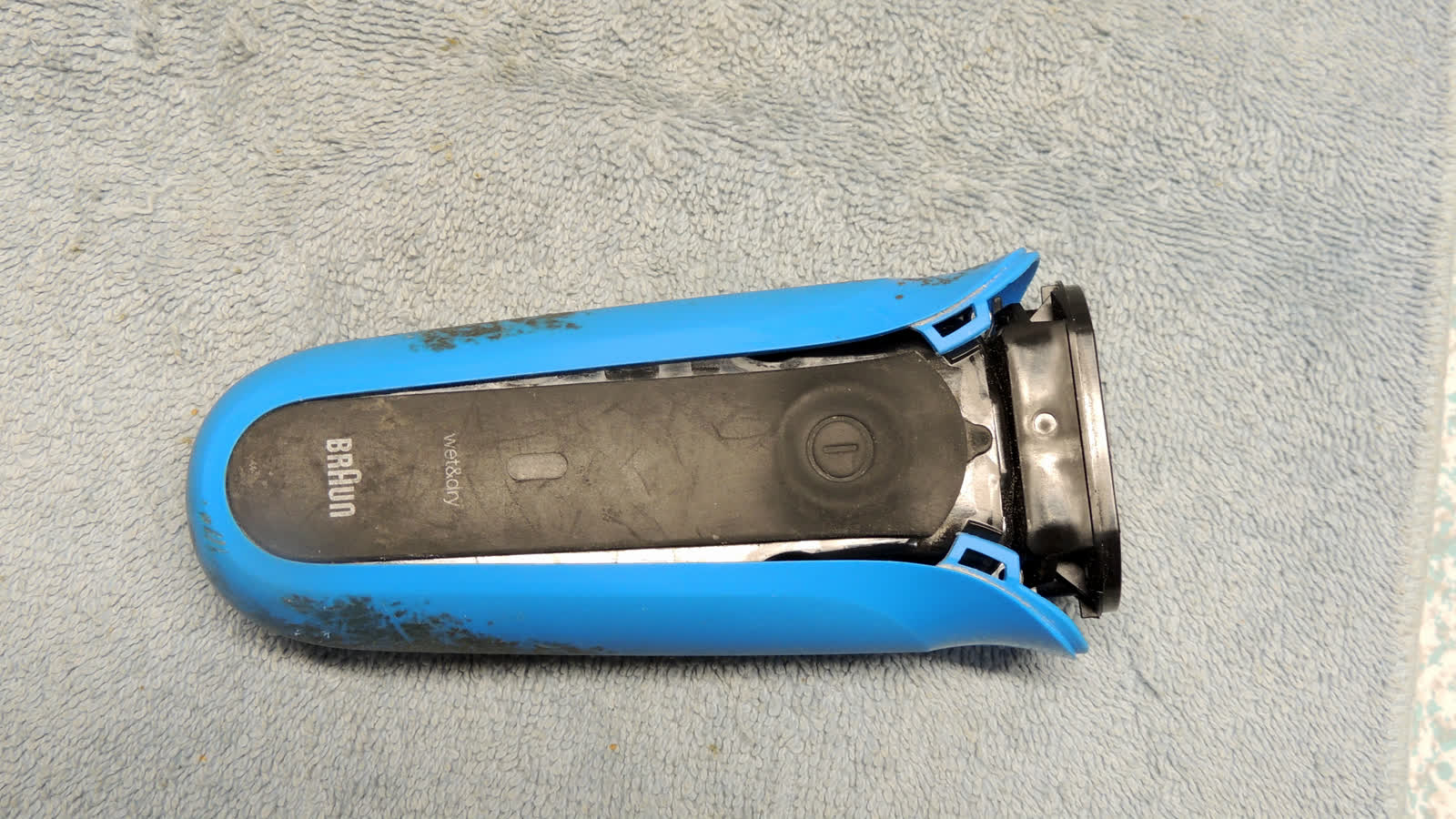
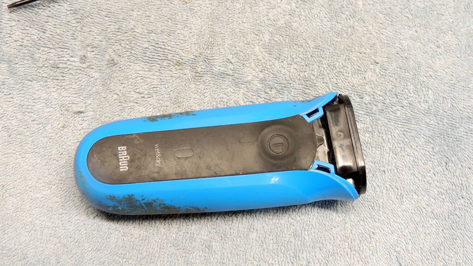
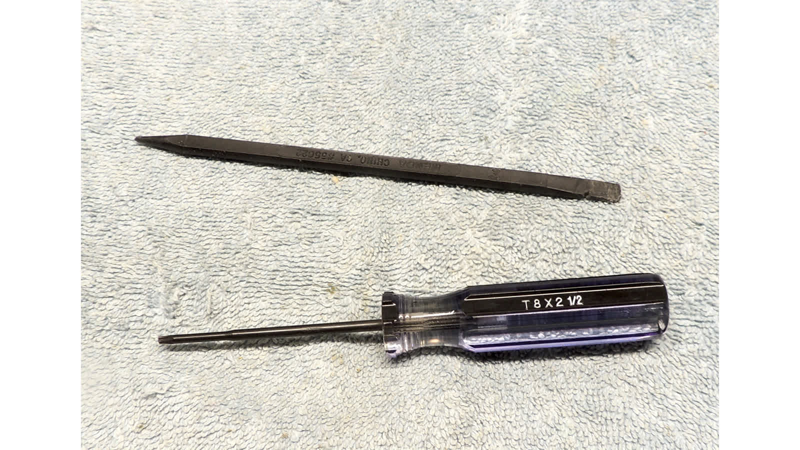
- tools needed: #8 torx, nylon stick, volt-meter   (optional: small flat-head screwdriver)

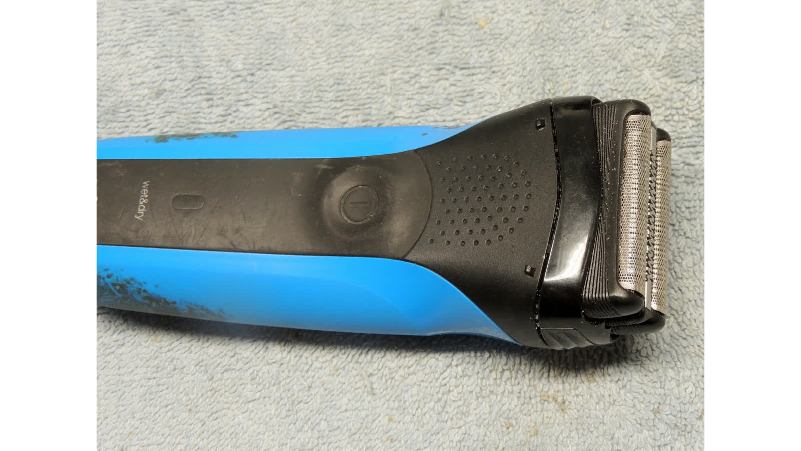
- remove cutter head
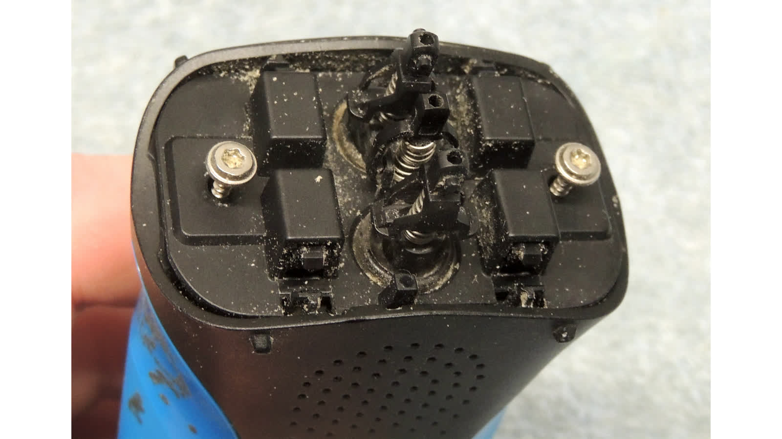
- remove two T8 screws holding outer head frame on
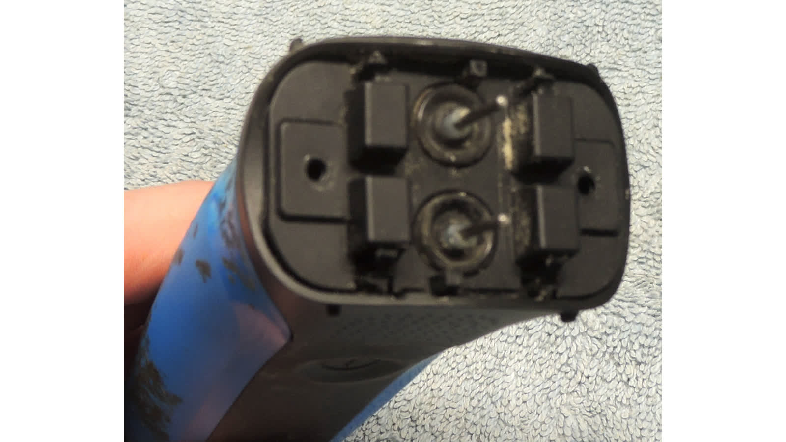
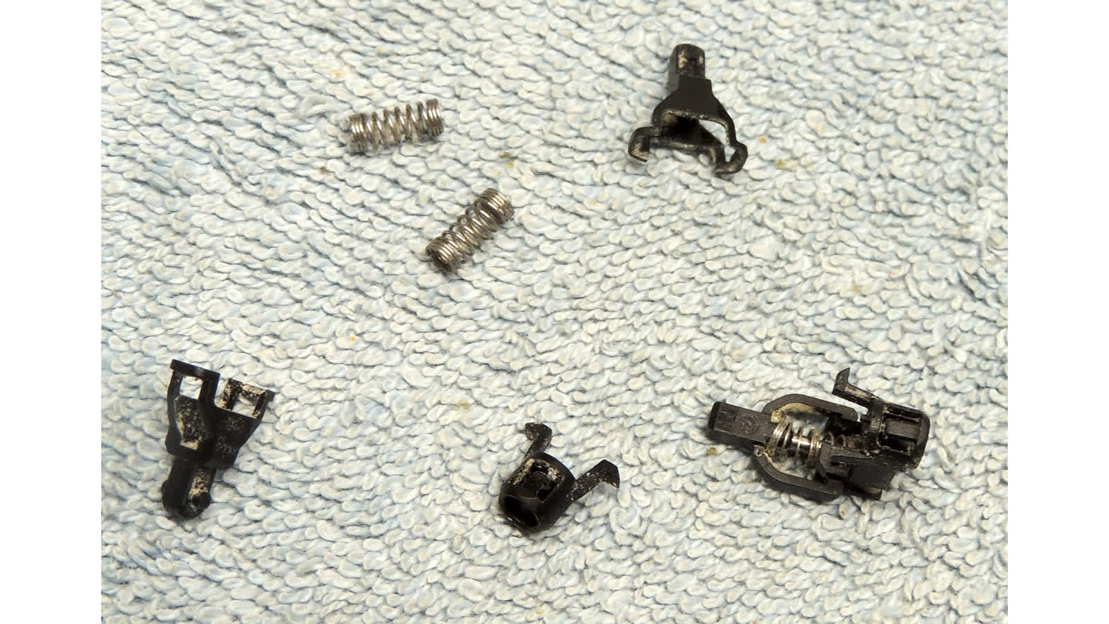
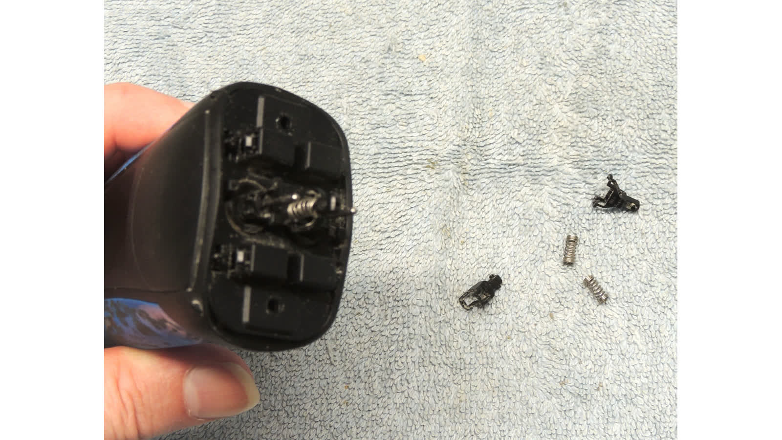
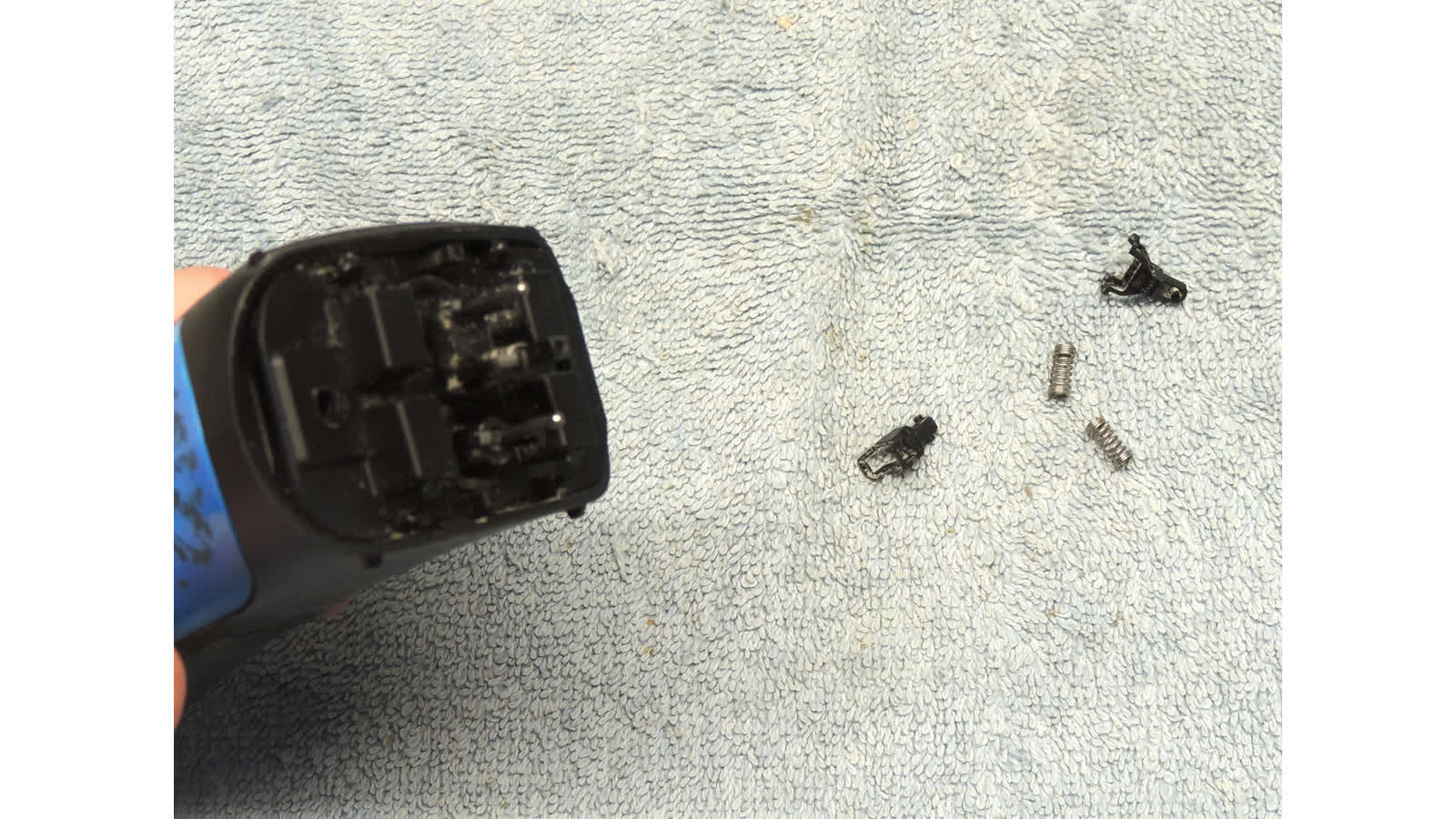
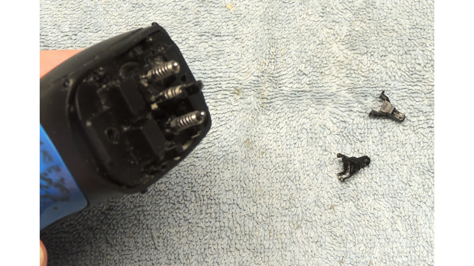
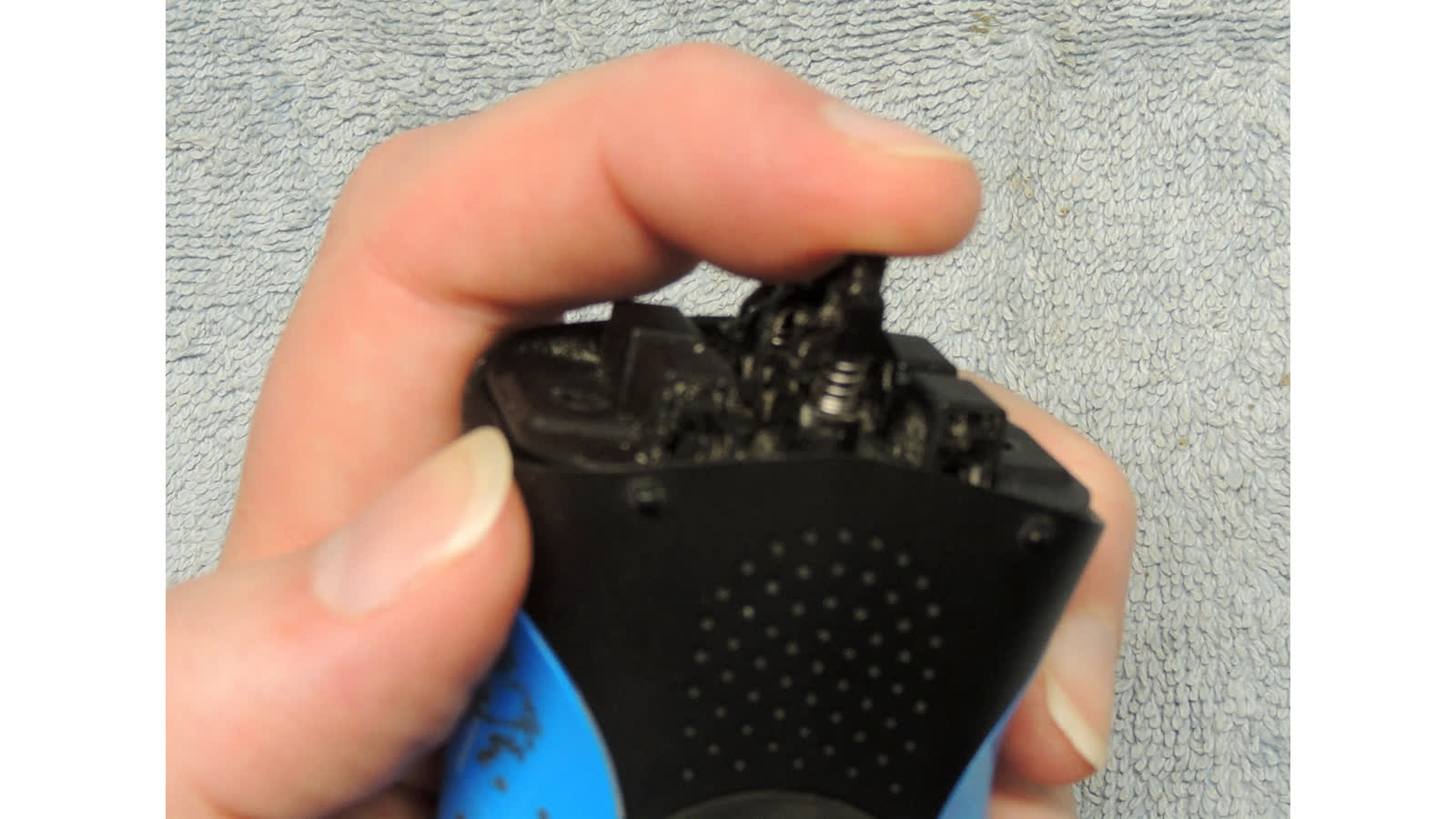
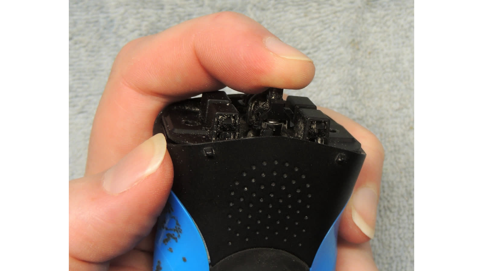
- carefully pry up on outer two post assemblies, pry from base, should pop up and off and fall apart
- store bits of assemblies, it's easy to lose a plastic part or a spring
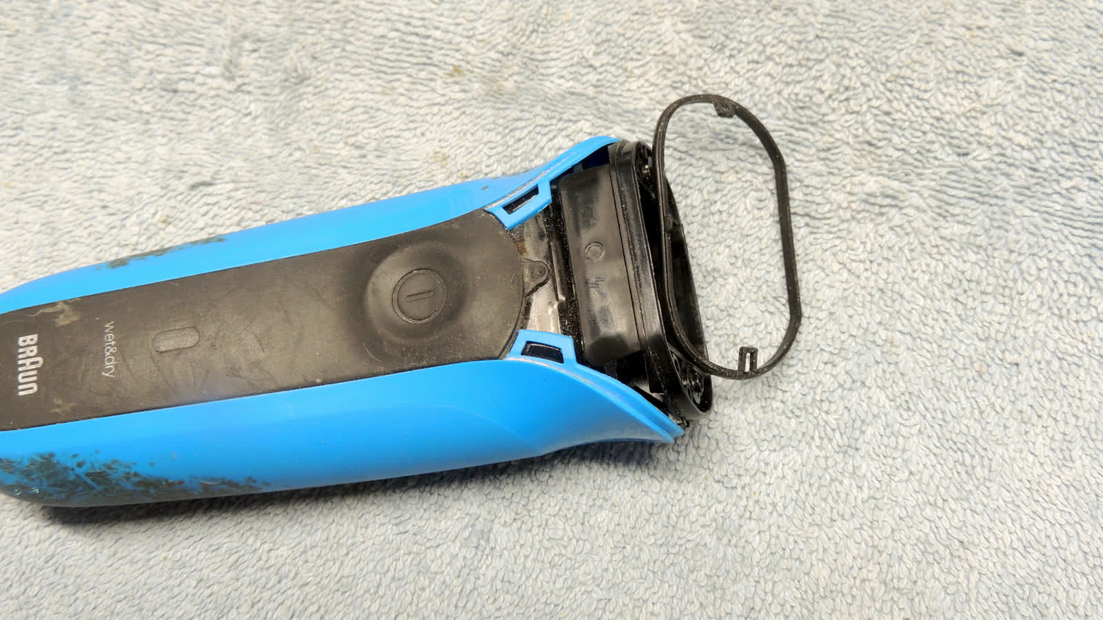
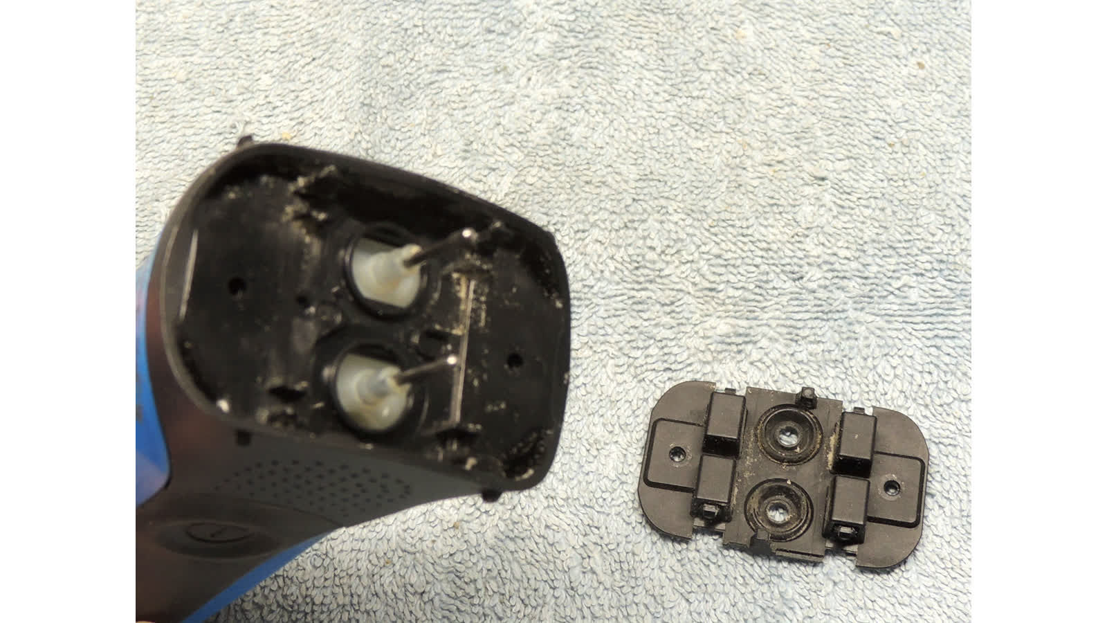
- pull head cover out of outer head to expose guide posts

- pry and pull the back side cover off (to reassemble, set down to one side, and slide into position)
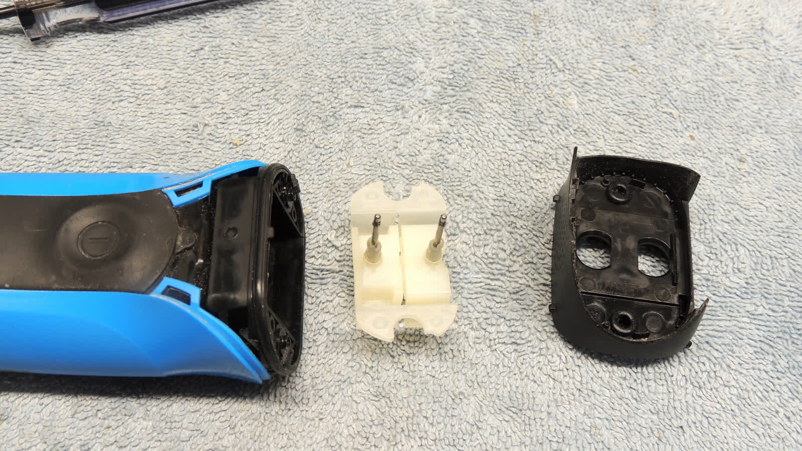
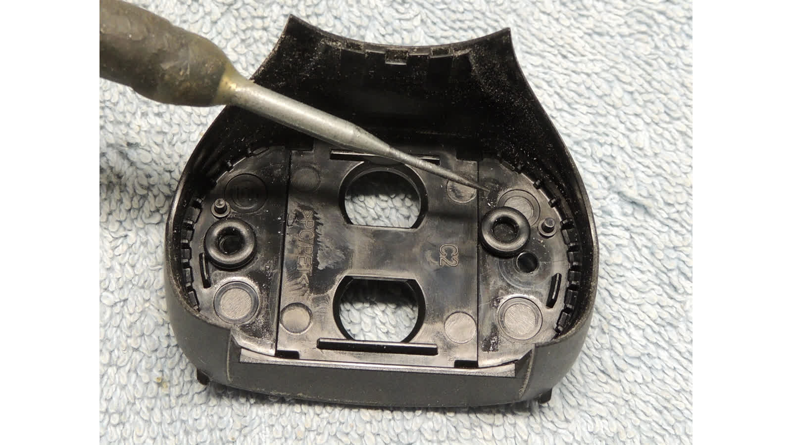
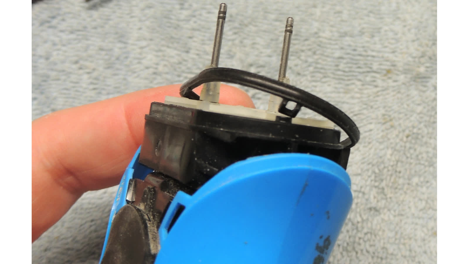
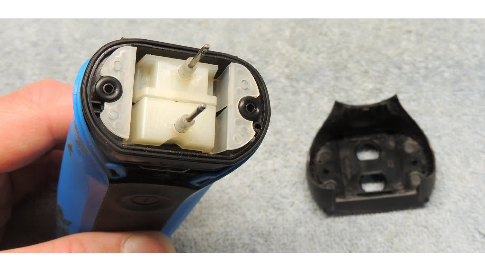
- pull inner head frame off to expose white translation guide, gasket, and o-rings
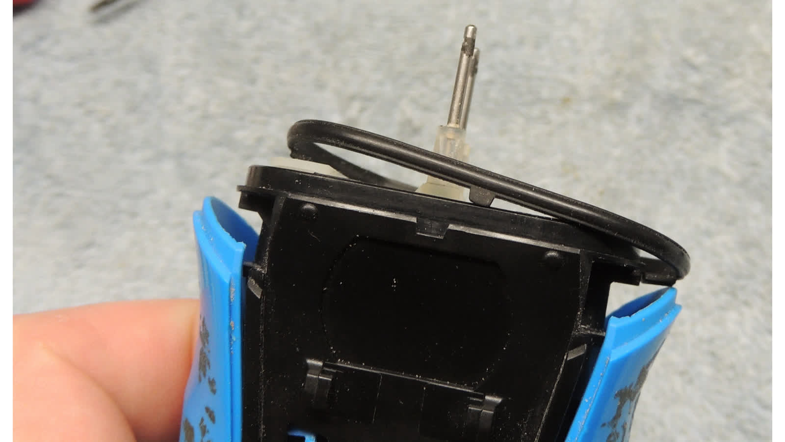
- remove o-rings, but leave gasket since it is trapped by the blue grip

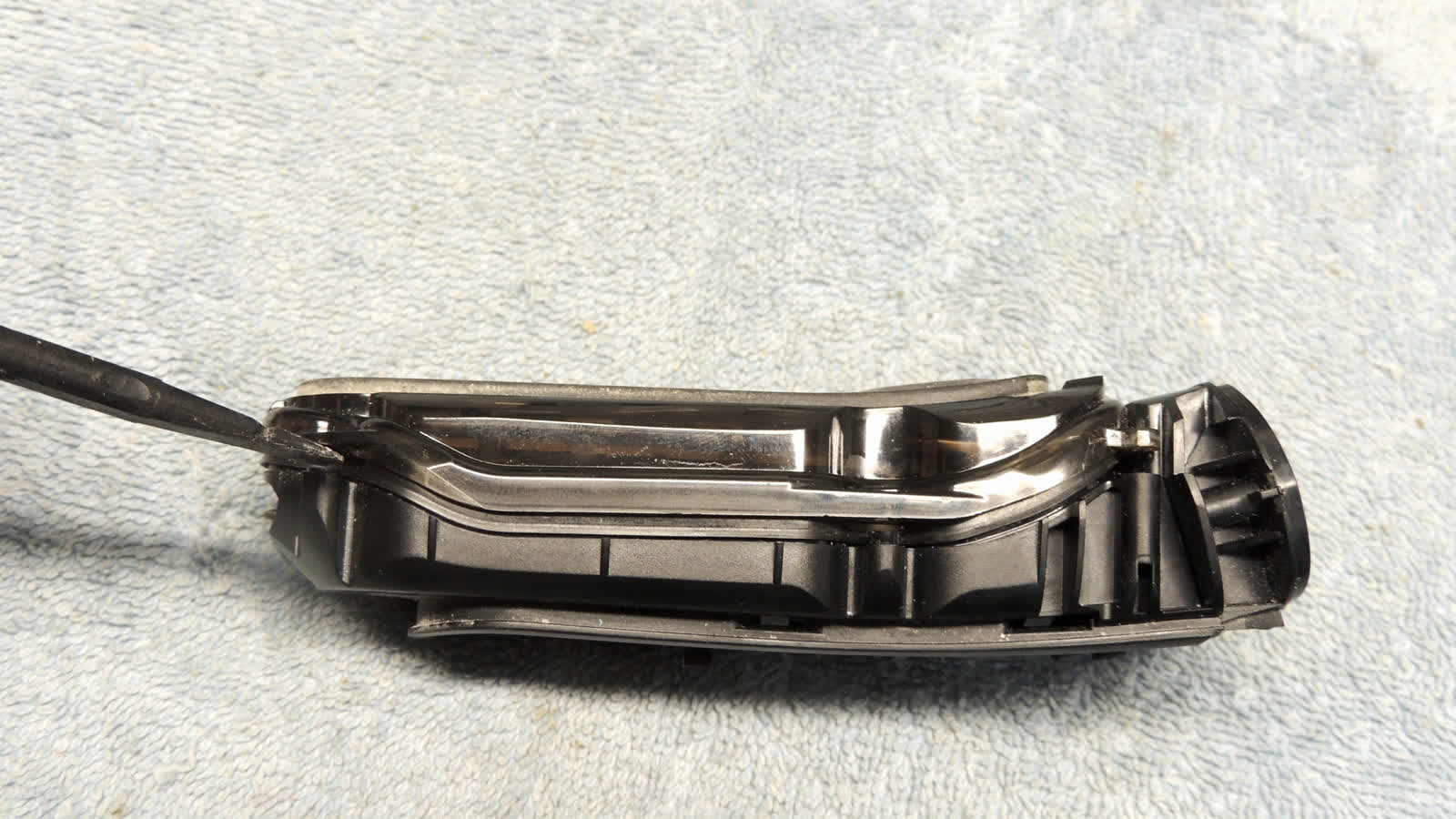
- pry edges of blue guide away from body (clips should yield on their own, do no pry the clips)
- carefully remove gasket (note key on one side)
- o-rings may have stuck to inner head frame, if so remove and set aside

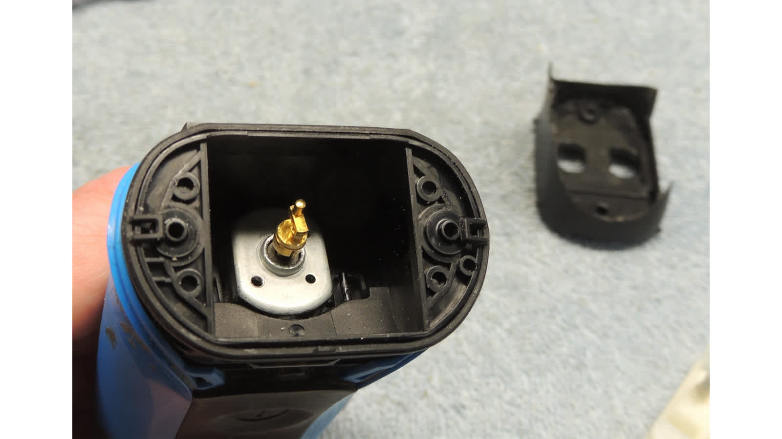
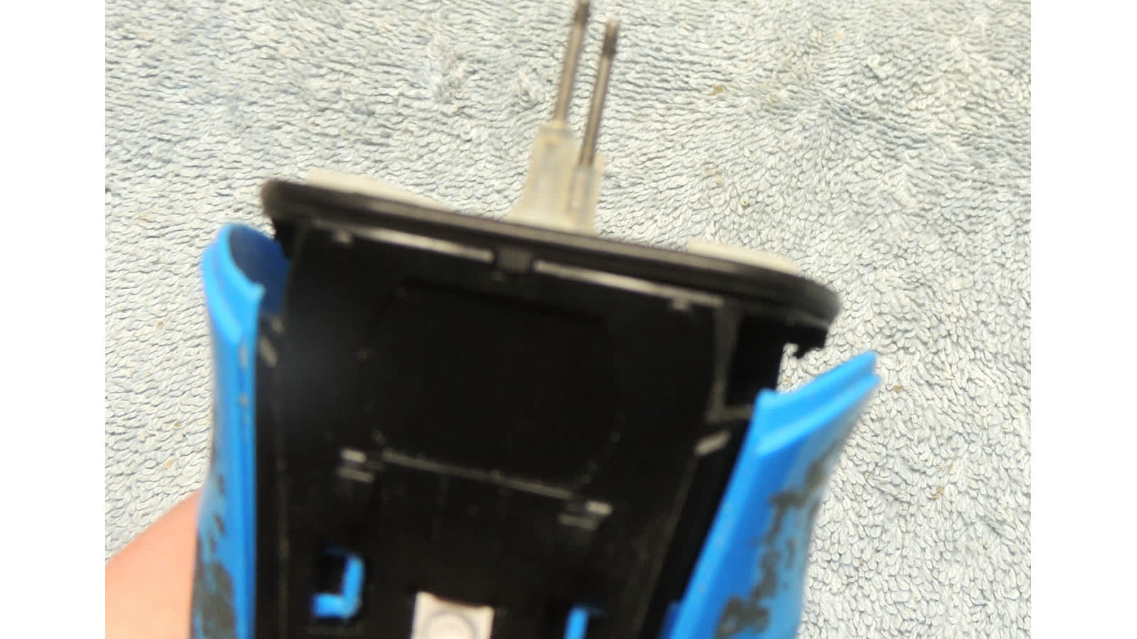
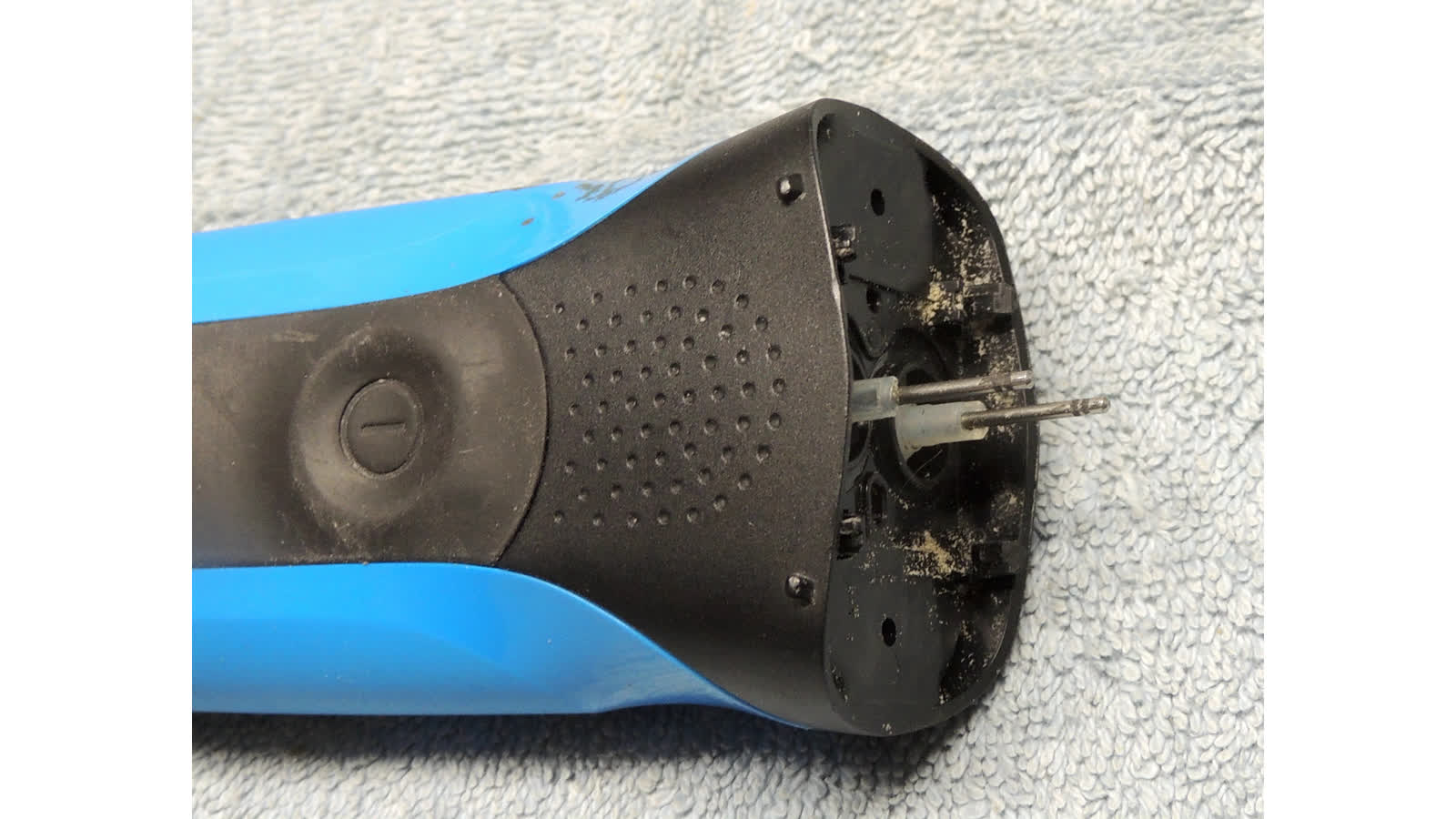
- remove white guide.  note position of gold motor head, it needs to be in that orientation when reassembling
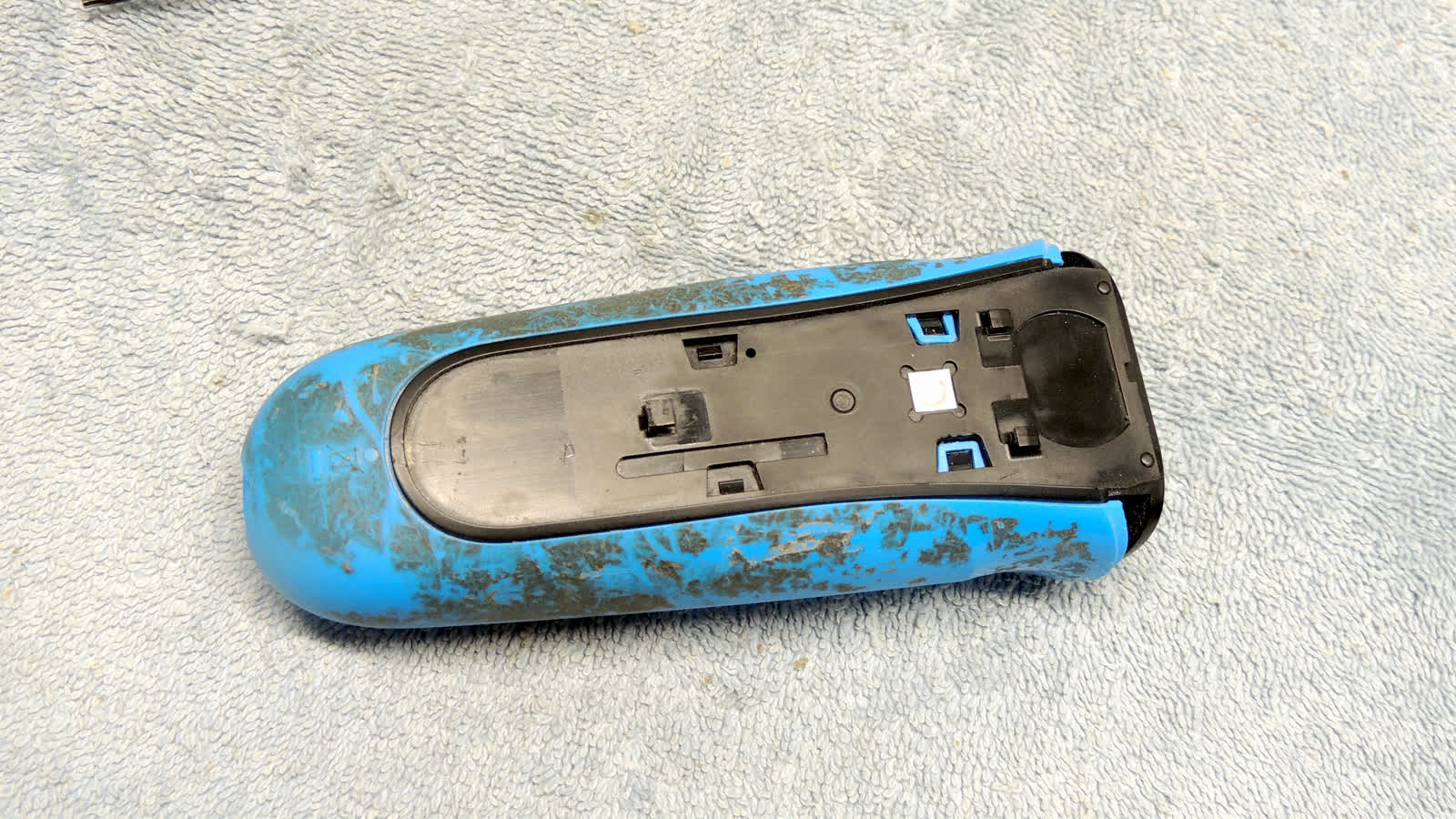
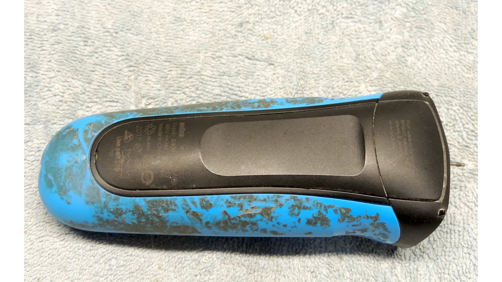
- pry and slide blue grip down off body (more difficult to remove than to reassemble)
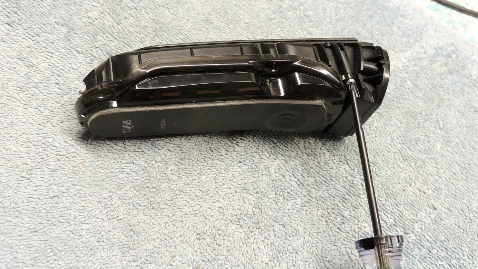
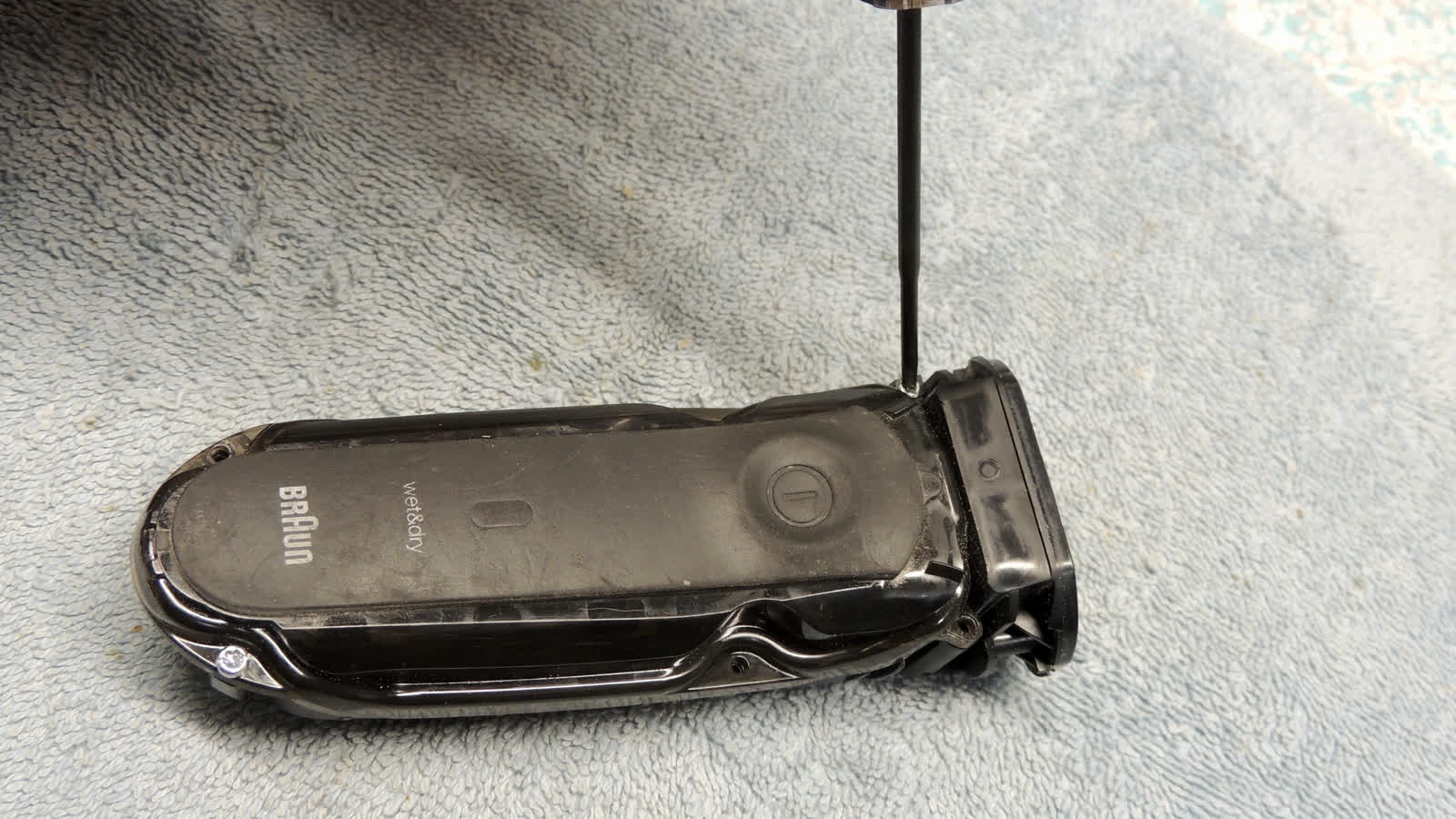
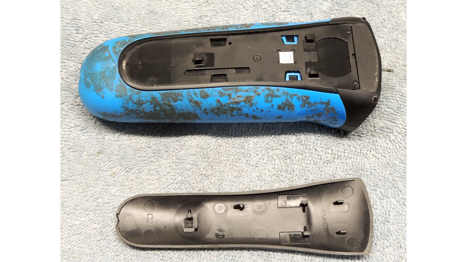
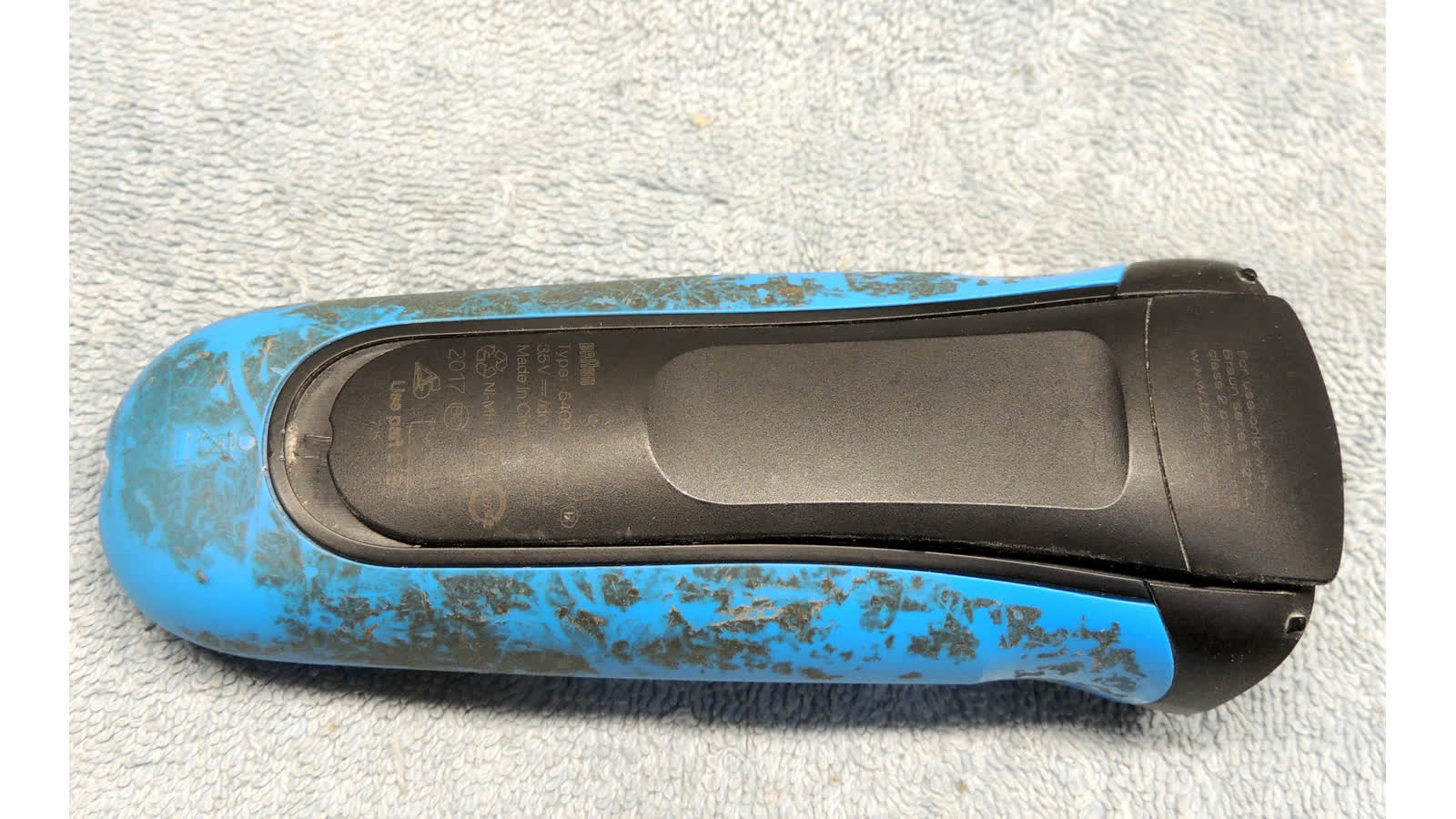
- remove four T6 screws holding body cover on (screws vary, some razors only use 2)
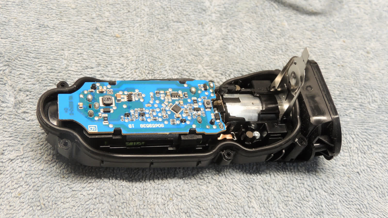
- use nylon stick to pry cover off body, exposing control board atop "power unit"

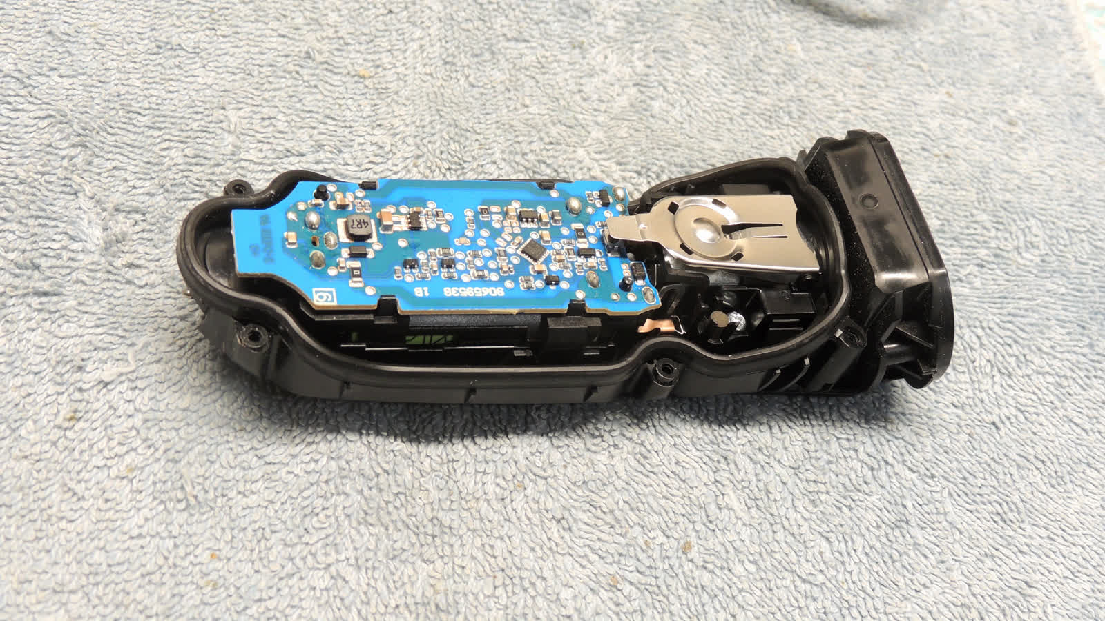
- raise button lever
- lift entire power unit straight up and out (copper clasps engage blades on motor)
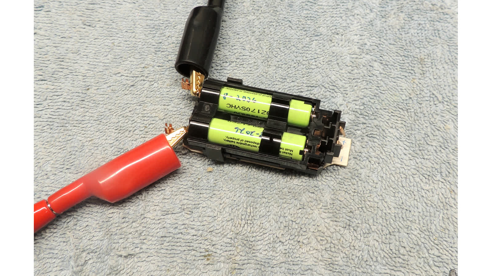
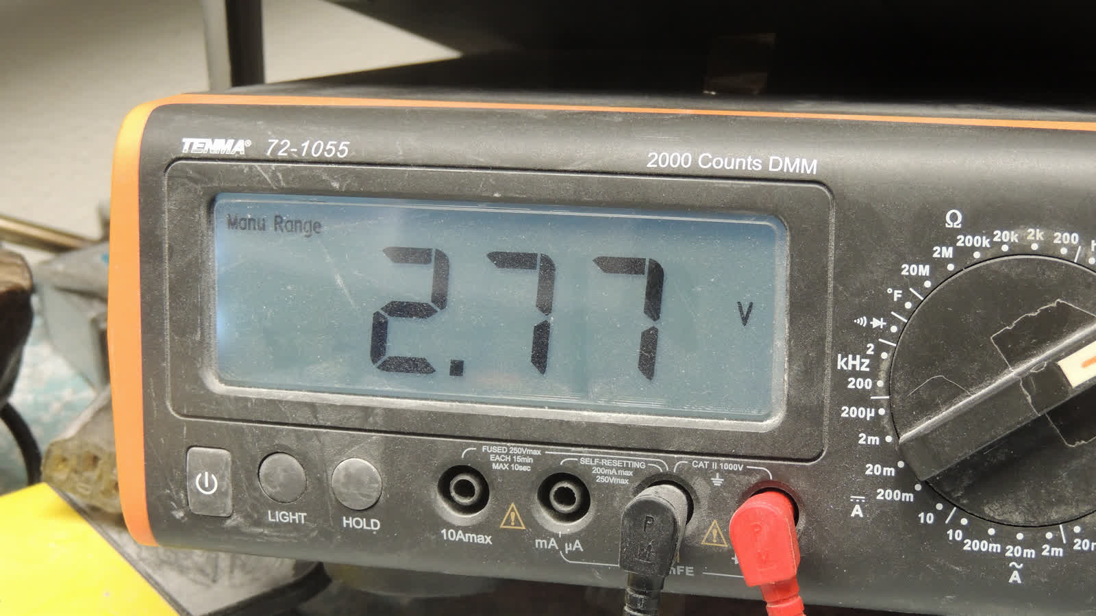
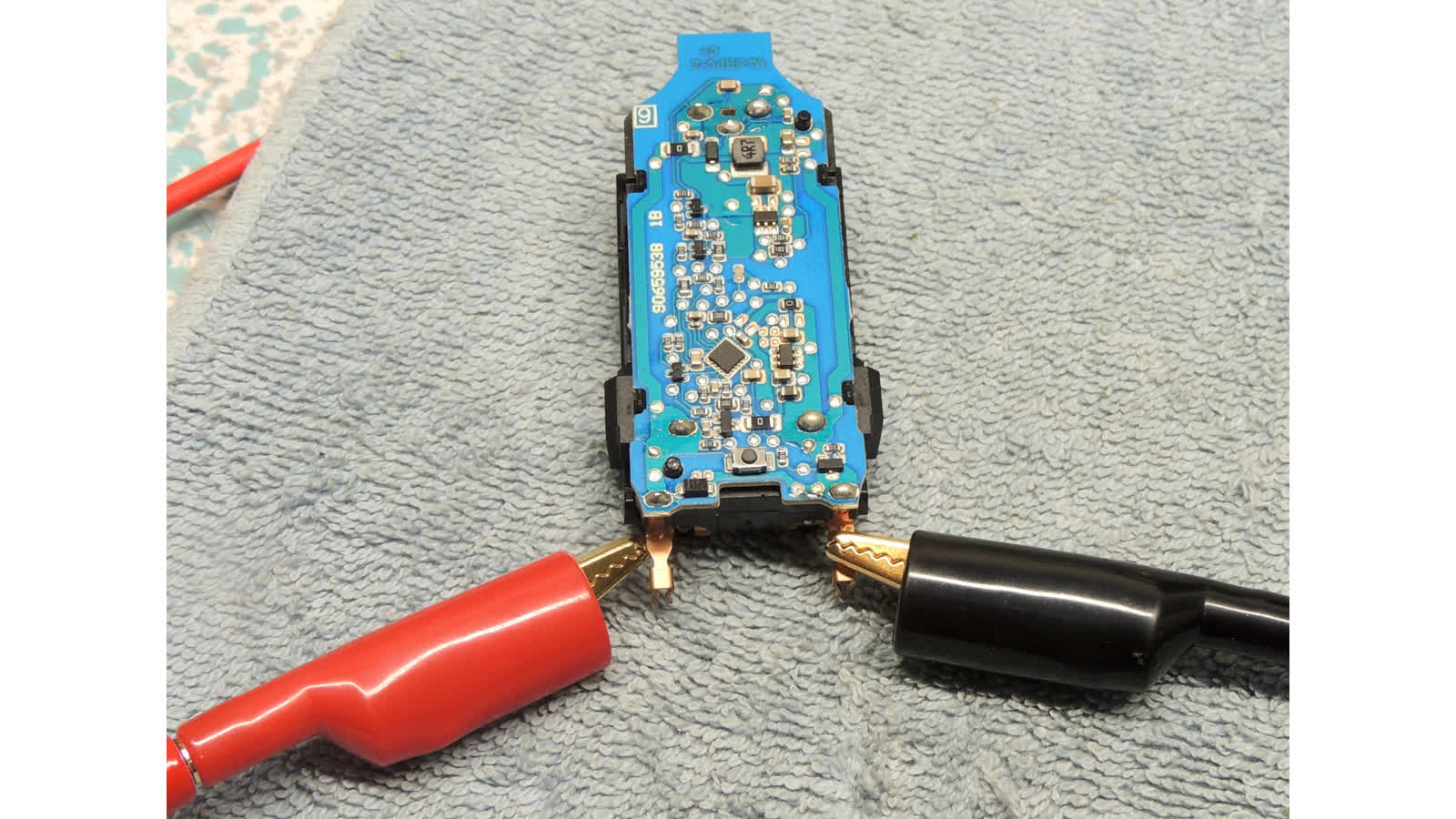
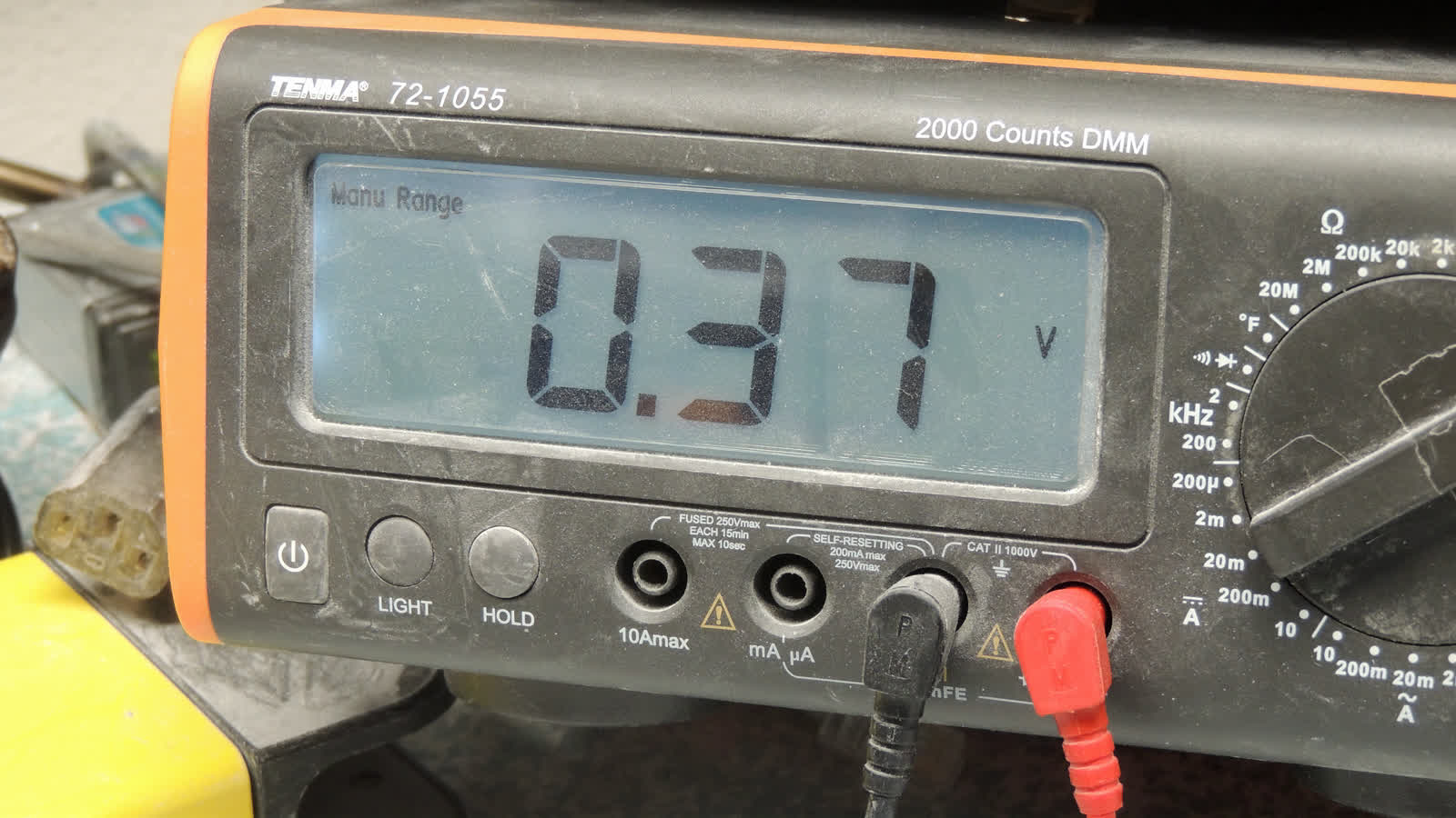
- verify low voltage on exposed clasps (should be around 0.37 volts, NOT 2.5-3v)

- suggest marking end of power unit board with "+" and "-" indicators since nothing is marked for polarity
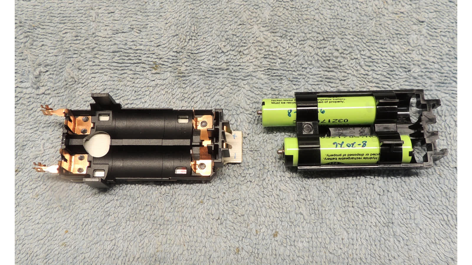
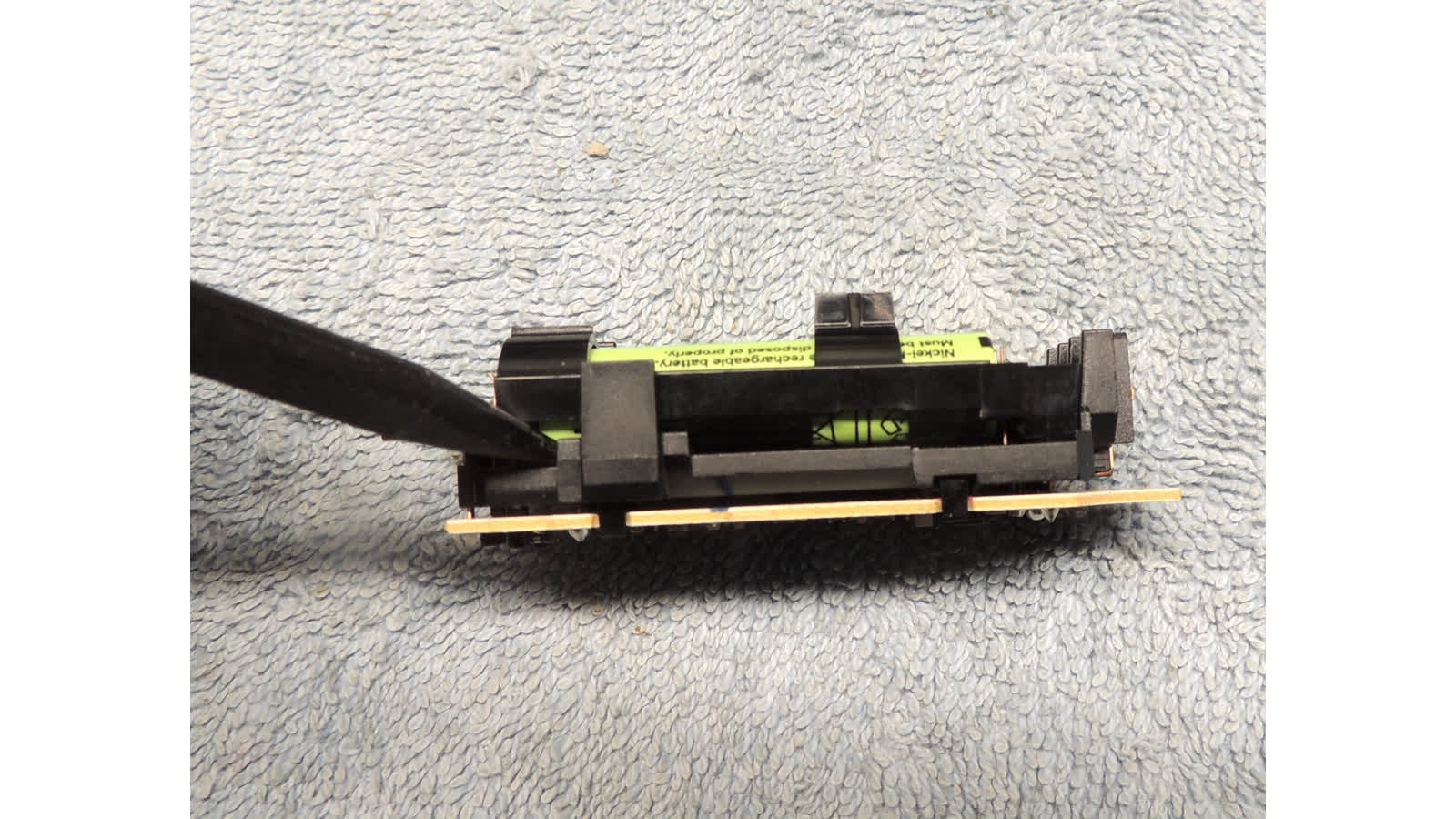
- use nylon stick to separate battery cage from power unit (pins on battery ends will snap out of their clips)
- slide out old cells
- mark new cells with date
- slide in new cells.  pay careful attention to polarity.


- set battery cage down in power unit
- test voltage on gold clips.  it MUST read low (0.37v) before proceeding!
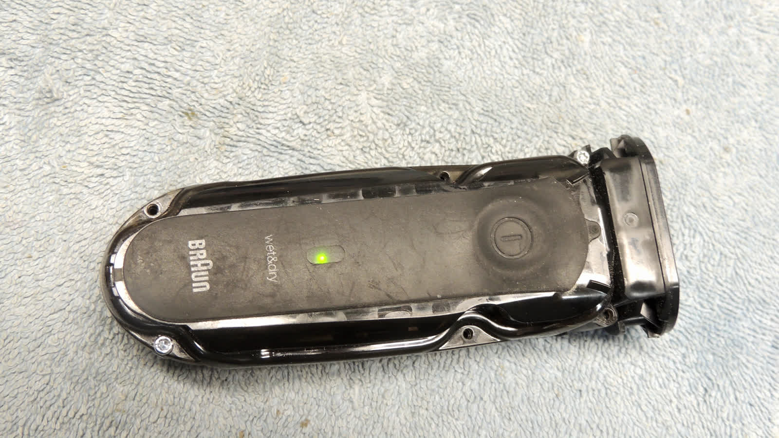
- if battery voltage reads high, (and most likely green light is on), press button to turn off power unit and
  wait for voltage on gold clips to drop to safe volage

- set power unit down in racor body
- verify gold clips are aligned with blades on power unit, and press down to dock with body
- press power button to verify motor runs, then press again to turn off

- fold button lever back down onto button
- install body cover and reinstall T8 screws

- slide blue grip back on (it only goes on one way, one U is longer than the other)
  DO NOT press in sides yes
- reinstall gasket.  note key on one side, and side loops must fit down around loops under the inner head
- squeeze grip to snap together with body

- adjust motor gold pin upward to align with white guide
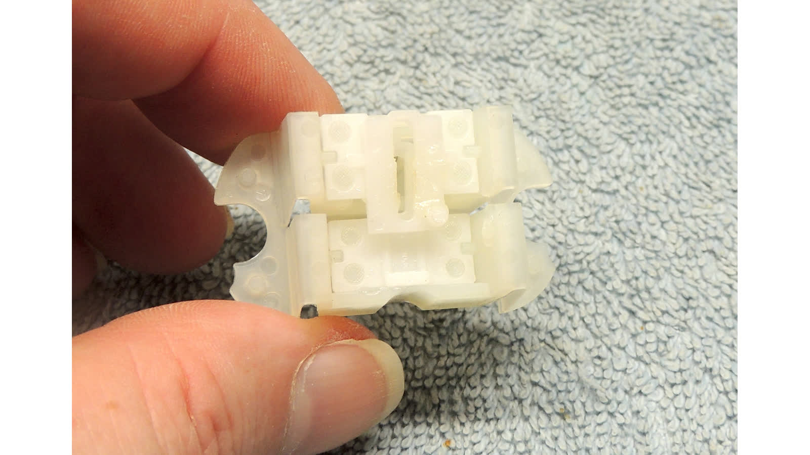
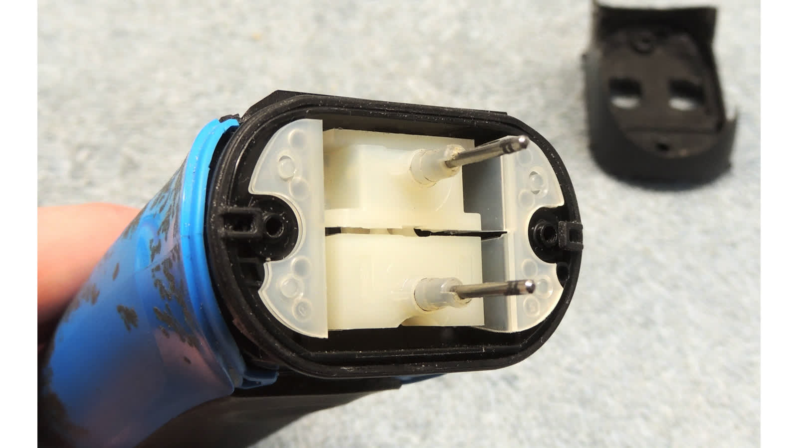
- reinstall white guide with open loop toard end to mate with gold pin
  DO NOT test motor now, white guide is not secure yet)
- make sure pins on lower lip of white guide are fully engaged with holes on inner head

- reinstsall o-rings on lower head screw hole posts
- press outer head down onto lower head
- set side cover down a bit to side of final position
- press/side side cover to lock into position

- press head cover back into place on posts (fits either way)
- reinstall two T-8 screws on head cover
- slide double-shaker assembly onto middle and one side post
- install base of single shaker onto remaining side post
- slide springs onto both side posts
- install top end of shakers onto posts (will not want to stay)
- carefully press top shakers down to compress springs and dock with lower shakers

- press power button to test shakers.  press again to turn off
- reinstall cutter head