back to Ramsey DF-1
DF-1 board defect repairs
DF-1 board defect repairs:
There are three fixes that need to be done to an original DF-1 to correct manufacturing/design mistakes:
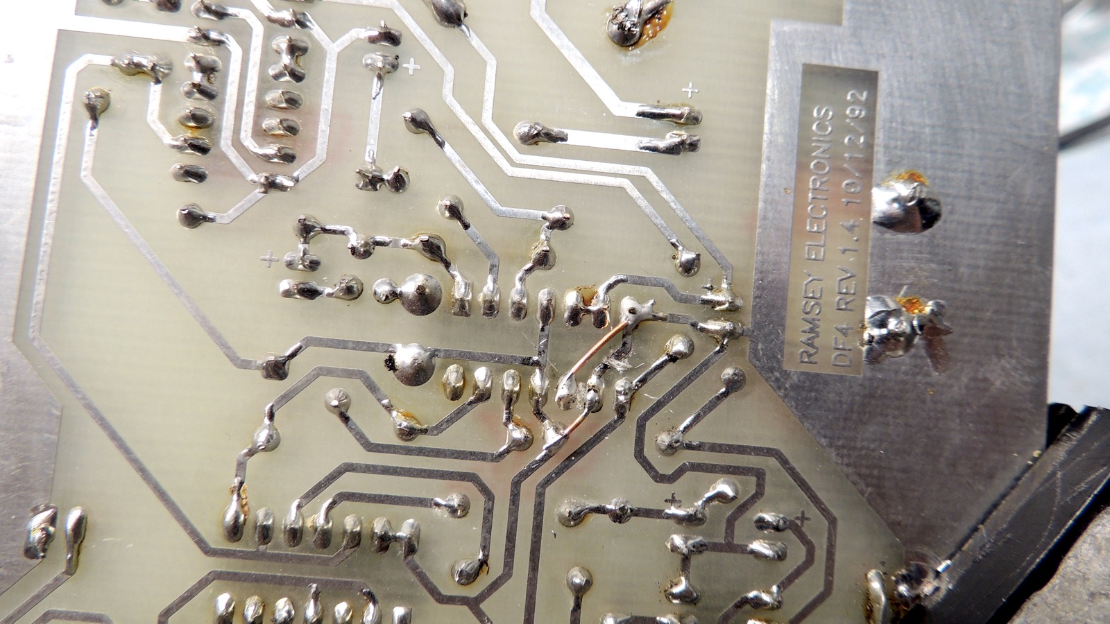
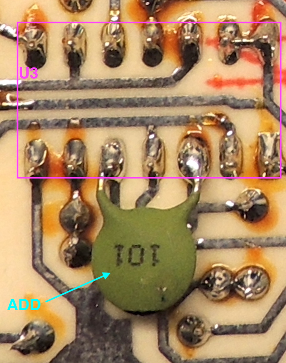
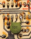
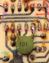
1: connect a 100pf ("101") cap between pins 3 and 5 of U3 (improves clock performance)
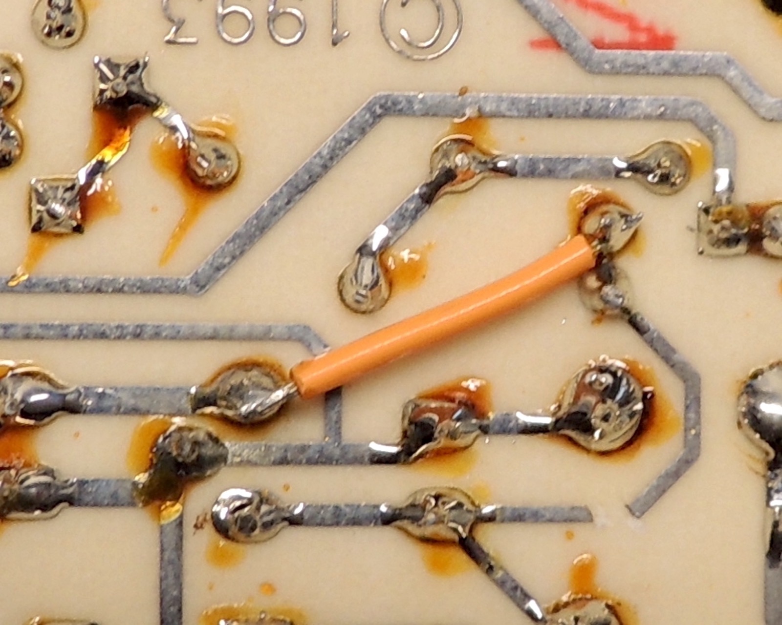
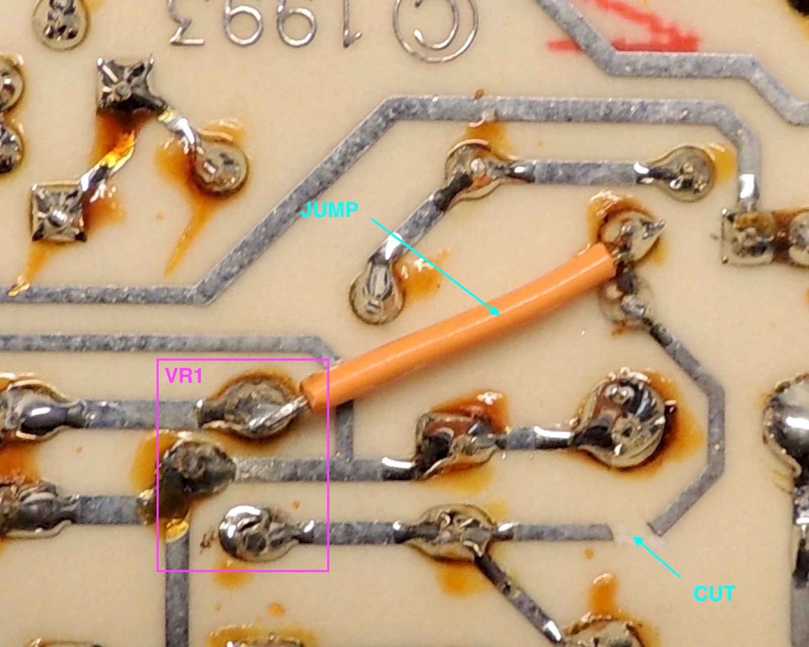
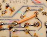
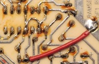
2: change +9 to Q1,R2 from +9 to +5v (improves TX protection)
- cut trace between C13+ and Q1,R2
- add jumper between Q1,R2 and VR1-out
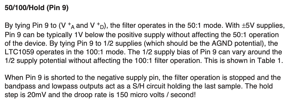
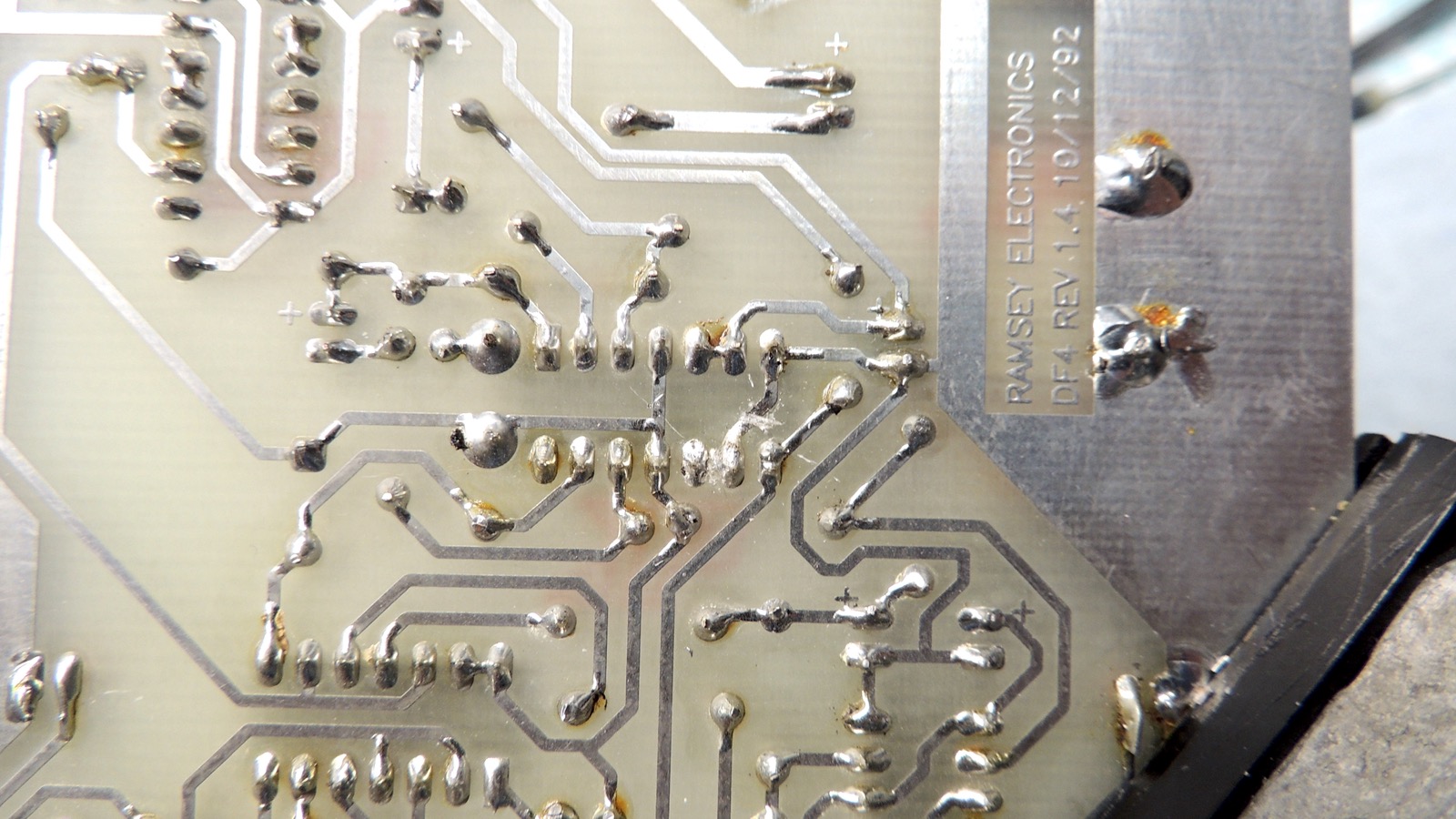
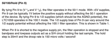
3: fix U2's 50/100/HOLD pin (HOLD is selected due to being grounded, 100 should be selected with 4.5v)
- cut trace between U2 pins 7 and 9
- cut trace between U2 pins 9 and 10
- add jumper between U2 pins 9 and 11
- add jumper between C12- and ground plane
Fix 3 will vary depending on board revision. What's important is you get U2-9 off ground and connect it to
the "half vcc" voltage (4.5v) on C12+ that's already running to U2-4 and U2-11. On most boards, a ground
trace runs through U2-9 and continues on to ground other components. You need to supply them with ground
after you isolate U2-9.
Fix 3 only applies on the circuit board, since the schematic in the manual is correct.
Fixes 1 and 2 are optional, but fix 3 is ESSENTIAL. (it won't work without it)
Before fix 3 is applied, the unit will not show any consistent left/right light, and the phase difference
meter will not move up much regardless of which direction the antennas are turned. Turning up the sensitivity
will not help.
older revision board showing same defect
|
|
|
|
|

|
| 50-100-HOLD pin |
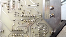
board rev 1.4 repair A |
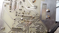
board rev 1.4 repair B |
fix 1 |
fix 1 annotated |
fix 2 |
|
|

|
|
|
|
| fix 2 annotated |
fix 3 |
fix 3 annotated |
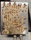
fixed board |
|
|
highest resolution images
last updated 05/10/2025 at 21:43:04 by make_www_index.command version 2025.05.08.A